Hola a todos!
ACLARO QUE SOY UN NEÓFITO EN ESTO
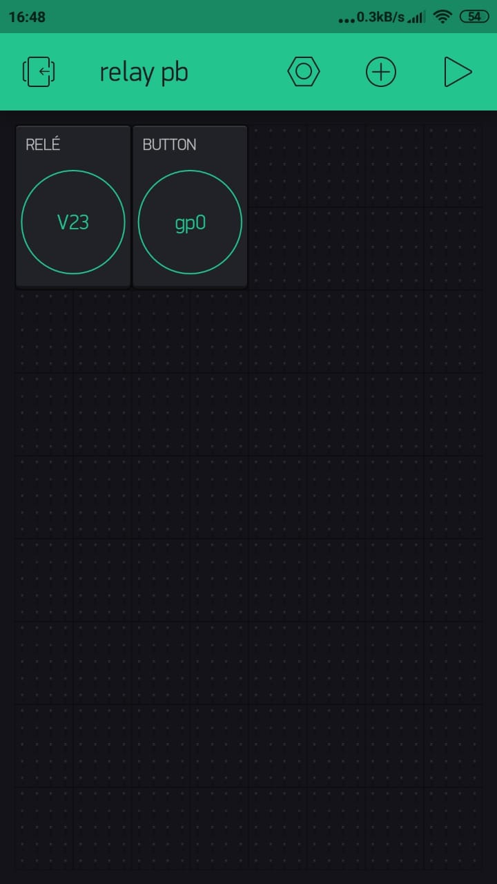
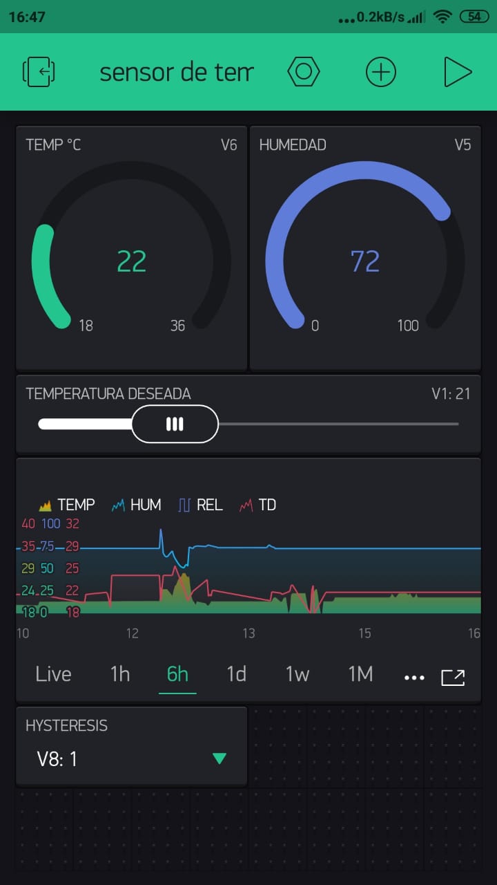
Luego de luchar durante mas de 3 días y perder el sueño por los enojos y el esfuerzo mental, finalmente conseguí hacer funcionar un sistema de control de temperatura remoto vía wifi (ESP8266+DHT11+Cargador de celular) y un receptor que se encarga de activar la caldera (ESP8266+Relay+Cargaor de celular)
Hi all!
LET ME FIRST BE CLEAR… I AM A NEOPHYTE IN THIS
After struggling for more than 3 days and losing sleep due to anger and mental effort, I finally managed to operate a remote temperature control system via wifi (ESP8266 + DHT11 + Cell phone charger) and a receiver which is responsible for activating the boiler (ESP8266 + Relay + Cell phone charger)
/*
PROYECTO ESCRITO POR Emanuel Barboni
Basado en el proyecto ThermoX de Eric "chrome1000"
SENSOR DE HUMEDAD Y TEMPERATURA BASADO EN ESP8266+DHT11
*/

#define BLYNK_PRINT Serial
#include <ESP8266WiFi.h>
#include <BlynkSimpleEsp8266.h>
#include <DHT.h>
#define DHTTYPE DHT11
#define DHTPIN  2

BlynkTimer timer; // cada un determinado tiempo envia la medición

float TempDes = 21;
float TempAct;
int TempCorrection = 0;
int UpdateFrequency = 5000L; //Update frequency in milliseconds
float LastRead;
float Hu;

int Hysteresis_W = 1; //Summer and Winter hysteresis levels

char auth[] = "XXXXXXXX"; //Enter the Auth code which was send by Blink
char ssid[] = "XXXXXXXXX";  //Enter your WIFI Name
char pass[] = "XXXXXXXXX";  //Enter your WIFI Password

WidgetBridge bridge1(V23); //Initiating Bridge Widget on V1 of Device A

DHT dht(DHTPIN, DHTTYPE, 11); // 11 works fine for ESP8266


void setup() {

  Serial.begin(115200);
  Blynk.begin(auth, ssid, pass);  // Call blynkAnotherDevice every second
  timer.setInterval(4000L, TempUpdate); // EJECUTA MEDICION CADA 4 SEGUNDOS
  dht.begin();
}

// empareja la temperatura deseada con el slider
BLYNK_WRITE(V1){
  TempDes = param.asInt();
  Blynk.virtualWrite(1,TempDes);
}

// empareja la Estación deseada con el botón
BLYNK_WRITE(V8){
  Hysteresis_W = param.asInt();
  Blynk.virtualWrite(8,Hysteresis_W);
}


//**/*/*/*/*/*/*/*/*/*/*/*/*/*/*/*/**//
// bridge the radiator sensor on or off

void TempUpdate () {

  float ReadF = dht.readTemperature();
  float Hu = dht.readHumidity();

  if (isnan(Hu) || isnan(ReadF)) {
    Serial.println("Failed to read from DHT sensor!");
    return;

  //Emision a la app para monitorear
  Blynk.virtualWrite(V5, Hu);
  }
  if (isnan(ReadF)) {
    return;
  }

  else   { //Read gets averaged with previous read and limited to 1 degree at a time change
    int TempAvg = (int)((ReadF + LastRead + (2 * TempCorrection)) / 2);
    if (TempAvg >= TempAct + 1) {
      TempAct = TempAct + 1;
    }
    if (TempAvg <= TempAct - 1) {
      TempAct = TempAct - 1;
    }

    LastRead = ReadF;
  }
  Blynk.virtualWrite(V6, TempAct); //Report actual temperature in app

    if (TempAct < TempDes) {
      bridge1.digitalWrite(0, LOW);  // Digital Pin 2 on the second board will be set HIGH
      bridge1.virtualWrite(V23, 1); // Sends 1 value to BLYNK_WRITE(V23) handler on receiving side.
    }
    else if (TempAct >= (TempDes + Hysteresis_W)) {
      bridge1.digitalWrite(0, HIGH);  // Digital Pin 2 on the second board will be set HIGH
      bridge1.virtualWrite(V23, 0); // Sends 1 value to BLYNK_WRITE(V23) handler on receiving side.
    }

}

BLYNK_CONNECTED() {

  bridge1.setAuthToken("XXXXXXXXX"); // Place the AuthToken of the second hardware here
}


// the loop function runs over and over again forever
void loop() {

  Blynk.run();
  timer.run();
  yield();
}
Programa para el lado del Relay
Relay side program
/*
PROYECTO ESCRITO POR Emanuel Barboni
Basado en el proyecto Blynk Bridge  www.geekstips.com
SENSOR DE HUMEDAD Y TEMPERATURA BASADO EN ESP8266+Relay v4.0
*/

#define BLYNK_PRINT Serial
#include <ESP8266WiFi.h>
#include <BlynkSimpleEsp8266.h>

// You should get Auth Token in the Blynk App.
// Go to the Project Settings (nut icon).
char auth[] = "XXXXXXXXXXXXXXXXX";

// Your WiFi credentials.
// Set password to "" for open networks.
char ssid[] = "XXXXXXX";
char pass[] = "XXXXXXX";


// This code will update the virtual port 5
BLYNK_WRITE(V23) {
  int pinData = param.asInt();
  Blynk.virtualWrite(V24, 255);// Avisa el estado al led
}

void setup(){
  Serial.begin(115200);
  Blynk.begin(auth, ssid, pass);
}

void loop(){
  Blynk.run();
}
Espero les sea útil como lo es para mi.
Saludos!
I hope you find it useful as it is for me.
Regards!