Combining two sketches, help needed

I am working on a automation that will allow me to control the dial on my propane heater at my cabin remotely. I would also like to be able to measure the temperature inside and outside the cabin and manage remotely with Blynk. For this project I have a

NodeMCU with WiFi
DS18B20 temperature sensors
MG995 Servo Motor

I have been successfully able to run a program which allows activation of the servo and I have been able to run a program that reads the data from a single thermometer. I have attempted to combine the sketches, however when uploaded to the board I am unable to read temperature or control the servo via Blynk. I am relatively new to coding, and I imagine I am making an error somewhere.

Temperature Code - Single sensor


#include <Blynk.h>
#include <SimpleTimer.h>
#define BLYNK_PRINT Serial       
#include <BlynkSimpleEsp8266.h> 

#include <OneWire.h>
#include <DallasTemperature.h> 
#define ONE_WIRE_BUS 2         
OneWire oneWire(ONE_WIRE_BUS);
DallasTemperature sensors(&oneWire);

char auth[] = "my auth";
char ssid[] = "my wifi";
char pass[] = "my password";

SimpleTimer timer;

int roomTemperature;            // Room temperature in F

void setup()
{
  Serial.begin(9600);
  Blynk.begin(auth, ssid, pass);

  while (Blynk.connect() == false) {
    // Wait until connected
  }

  sensors.begin();                      
  sensors.setResolution(10);            

  timer.setInterval(2000L, sendTemps);   
}

// Notice how there is very little in the loop()? Blynk works best that way.
void loop()
{
  Blynk.run();
  timer.run();
}

// Notice how there are no delays in the function below? Blynk works best that way.
void sendTemps()
{
  sensors.requestTemperatures();                 
  roomTemperature = sensors.getTempFByIndex(0);   
  Blynk.virtualWrite(1, roomTemperature);        
}

Temperature Code - Single sensor


#define BLYNK_PRINT Serial

#include <ESP8266WiFi.h>

#include <BlynkSimpleEsp8266.h>

#include <Servo.h>

char auth[] = "my auth";
char ssid[] = "my wifi";
char pass[] = "my password";

Servo servo;

BLYNK_WRITE(V3) {

servo.write(param.asInt());

}

void setup() {

Serial.begin(9600);

Blynk.begin(auth, ssid, pass);

servo.attach(15); 

}

void loop()

{

Blynk.run(); 

}

Combined Code - My Attempt, does not run

#define BLYNK_PRINT Serial
#include <Blynk.h>
#include <BlynkSimpleEsp8266.h>
#include <ESP8266WiFi.h>
#include <Servo.h>
#include <OneWire.h>
#include <DallasTemperature.h> 
#define ONE_WIRE_BUS 2 //D4

OneWire oneWire(ONE_WIRE_BUS);
DallasTemperature sensors(&oneWire);

char auth[] = "my auth";
char ssid[] = "my wifi";
char pass[] = "my password";

Servo servo;

BLYNK_WRITE(V3) {

servo.write(param.asInt());

}

SimpleTimer timer;

int roomTemperature; 

void setup()
{
Serial.begin(9600);
Blynk.begin(auth, ssid, pass);

while (Blynk.connect() == false) 
servo.attach(15); {
  }

sensors.begin();                       
sensors.setResolution(10);     

  timer.setInterval(2000L, sendTemps);   
}

// Notice how there is very little in the loop()? Blynk works best that way.
void loop()

{
  Blynk.run();
  timer.run();
}

void sendTemps()
{
  sensors.requestTemperatures();               
  roomTemperature = sensors.getTempFByIndex(0);   getTempCByIndex(0) for celcius.
  Blynk.virtualWrite(1, roomTemperature);         
}


Again my goal is to control the servo along with two temperature probes remotely.  So far I have been able to get the servo to run with an individual program, and one temperature probe to work, my attempts have been unable to make two temperature probes read.

Any help or guidance in combing the two codes along with adding an additional temperature sensor would be greatly appreciated!

Thanks!

Scott

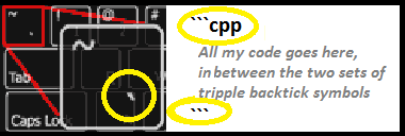
Please format posted code properly, as required in the Welcome Topic…

Blynk - FTFC

I don’t know if it matters, but the returned value is a float, not int

Index(0) is only one sensor, you’ll need an Index(1) for the second sensor.

To speed up readings (and to know which is where) I’m accessing the sensors by their unique ID instead. Setup like this:

const byte ONE_WIRE_BUS = 3;

OneWire oneWire(ONE_WIRE_BUS);
DallasTemperature DS18B20(&oneWire);

byte sensor1E[] = { 0x28, 0xFF, 0x65, 0x5B, 0x90, 0x15, 0x3, 0x1E };	
byte sensor4B[] = { 0x28, 0xFF, 0x9C, 0x5B, 0x90, 0x15, 0x3, 0x4B };

And my function is something like this:

float temp1E = DS18B20.getTempC(sensor1E);
float temp4B = DS18B20.getTempC(sensor4B);
		
Blynk.virtualWrite(6, temp1E);
Blynk.virtualWrite(5, temp4B);

The DS18B20:s EEPROM is specified to handle +50.000 rewrites (it stores the data before sending) without failure, but reading the sensors once every 2 seconds equals 43.200 readings a day! So I recommend that you ease up on frequency as a precaution.

Good luck! :slightly_smiling_face:

@skrankk in order to find each sensor’s unique ID, I have used this program, marked each address into a document, then marked each sensor with an identifying mark corresponding to the address in said document.

// This sketch looks for 1-wire devices and
// prints their addresses (serial number) to
// the UART, in a format that is useful in Arduino sketches
// Tutorial: 
// http://www.hacktronics.com/Tutorials/arduino-1-wire-address-finder.html

#include <OneWire.h>

OneWire  ds(3);  // Connect your 1-wire device to pin 3 (Arduino pin numbering)

void setup(void) {
  Serial.begin(115200);
  discoverOneWireDevices();
}

void discoverOneWireDevices(void) {
  byte i;
  byte present = 0;
  byte data[12];
  byte addr[8];
  
  Serial.print("Looking for 1-Wire devices...\n\r");
  while(ds.search(addr)) {
    Serial.print("\n\rFound \'1-Wire\' device with address:\n\r");
    for( i = 0; i < 8; i++) {
      Serial.print("0x");
      if (addr[i] < 16) {
        Serial.print('0');
      }
      Serial.print(addr[i], HEX);
      if (i < 7) {
        Serial.print(", ");
      }
    }
    if ( OneWire::crc8( addr, 7) != addr[7]) {
        Serial.print("CRC is not valid!\n");
        return;
    }
  }
  Serial.print("\n\r\n\rThat's it.\r\n");
  ds.reset_search();
  return;
}

void loop(void) {
  // nothing to see here
}

2 Likes

Hello again, I finally got my part from china and now I’ve completely forgotten where I was, as usual.
Gunner, The device finder code you have here, does it run on the node mcu esp8266?
That is all I have here.
I did upload it and went to serial monitor but didn’t see anything except some squares=backwards ? and3. I’m sorry I tried to but it wont copy/paste.
I did change the pin to 2 b/c that’s where I had the sensor plugged in D4 physical.

UPDATE
I changed your code back to the original pin3 and looked up which was gpio3 and that is the RX pin so I connected my sensor to that and tried to upload again and got stopped by
ERROR espcom-upload-mem-failed.
So I backed out, disconnected the gpio3 and loaded a good sketch and it uploaded fine. At least I didn’t ruin the board!
Am I completely off the beam again?

yes :slight_smile:

you can’t have anything hooked up to tx and rx pins when uploading sketch or trying to use serial monitor!

all the communication between pc and mcu is happening via tx and rx, so if you have a sensor on one of those, it will halt / interfere the data flow.

in extreme cases (when there are no other pins left) you can use those pins - but than you can’t use serial monitor nor upload sketch.

but usually it is best to leave them alone, and choose other gpio. for ds18 it is ok to use for example gpio 2, 4, 14, etc.

the trick is, esp mcu has lots of gpio with multiple functions, so, one always have to study the pinout, to know which pin does what.

I did upload it and went to serial monitor but didn’t see anything except some squares=backwards ? and3. I’m sorry I tried to but it wont copy/paste.
I did change the pin to 2 b/c that’s where I had the sensor plugged in D4 physical.
So what do you think happened on my first try?
Are we sure this code is meant for this board or is it for something else?

It should run on anything that runs Arduino code (C++ variant)… Arduino, ESP8266 based, ESP32… but you will need to tweek for actual pins used, etc…

I tried and the only result was as i said a bunch of squares followed by an equal sign and then backwards question marks with a 3 in the middle. I did change the pin b/c pin3 is RX on the board.

Sounds like a mismatched BAUD rate

you will need to adjust this speed to match whatever your MCU is set for

Sounds like you have the wrong baud rate set in your Arduino serial monitor.

Pete.

Thanks Greatly, that fixed it. Up until today I have never touched the baud rate in three projects. Of course up until today I’d never used the monitor.
Lear something every day. Known as Funstration.
To be continued, I’ve had enough fun for today.

Thanks Gunner, Thanks Pete

1 Like