Combining code

Hi,

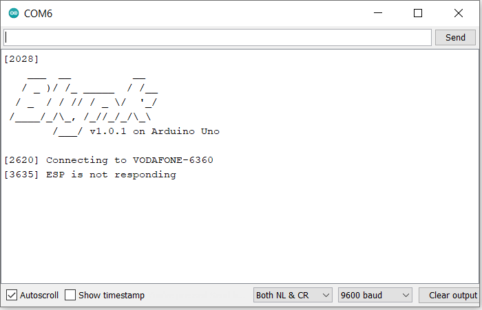
I have created code to control my sensor inputs and display them on a 20x4 LCD. I have also created code to connect to the Blynk app. These work seperatly but when i tried to combine them neither work. The LCD stops showing data once the Blynk code starts running in the setup and then the serial monitor does show that my board has connected to the wifi and is ready to start like it usually does.

Below is the code to connect to my Blynk app.


#define BLYNK_TEMPLATE_ID           "TMPL7mLWZCzi"
#define BLYNK_DEVICE_NAME           "Quickstart Device"
#define BLYNK_AUTH_TOKEN            "SQKj9qqAVwTsrLHimtkkdvSPMFuj8Ss_"


// Comment this out to disable prints and save space
#define BLYNK_PRINT Serial


#include <ESP8266_Lib.h>
#include <BlynkSimpleShieldEsp8266.h>


// Your WiFi credentials.
// Set password to "" for open networks.
char ssid[] = "Tenda_3165";
char pass[] = "JDwRadYk";

// Hardware Serial on Mega, Leonardo, Micro...
//#define EspSerial Serial

// or Software Serial on Uno, Nano...
#include <SoftwareSerial.h>
SoftwareSerial EspSerial(8,10); // RX, TX

// Your ESP8266 baud rate:
#define ESP8266_BAUD 9600

ESP8266 wifi(&EspSerial);

BlynkTimer timer;

// This function sends Arduino's up time every second to Virtual Pin (5).
// In the app, Widget's reading frequency should be set to PUSH. This means
// that you define how often to send data to Blynk App.
void myTimerEvent()
{
  // You can send any value at any time.
  // Please don't send more that 10 values per second.
  Blynk.virtualWrite(V5, millis() / 1000);
}


void setup()
{
  
  // Debug console
  Serial.begin(9600);

  // Set ESP8266 baud rate
  EspSerial.begin(ESP8266_BAUD);
  delay(10);

  Blynk.begin(BLYNK_AUTH_TOKEN,wifi, ssid, pass);
  // You can also specify server:
  //Blynk.begin(auth, wifi, ssid, pass, "blynk.cloud", 80);
  //Blynk.begin(auth, wifi, ssid, pass, IPAddress(192,168,1,100), 8080);

  // Setup a function to be called every second
  timer.setInterval(1000L, myTimerEvent);
}

void loop()
{
  Blynk.run();
  timer.run(); // Initiates BlynkTimer
}

Below is the code i used for displaying readings on my serial monitor


#include <DHT.h> // Includes the library needed to read the humidity sensor
#define type DHT11 // Defines the type of humidity sensor
int HumidityPin = 7; // indicates which pin the humidity sensor is connected to
DHT HT(HumidityPin, type); // Defines HT
float humidity; // declares the float called humidity


// Include the libraries we need for soil temperature sensor
#include <OneWire.h>
#include <DallasTemperature.h>

// Data wire is plugged into port 9 on the Arduino for soil temperature sensor
#define ONE_WIRE_BUS 9

// Setup a oneWire instance to communicate with any OneWire devices (not just Maxim/Dallas temperature ICs)
OneWire oneWire(ONE_WIRE_BUS);

// Pass our oneWire reference to Dallas Temperature. 
DallasTemperature sensors(&oneWire);

// arrays to hold device address for soil temp
DeviceAddress insideThermometer;


//Declare output pins for LEDs which will replace the humidifier, water pump and heat mat
int HumidityLED = 13;  // LED acting in place of humidifier is powered from pin 13

int HeatLED = A4;  // LED acting in place of heat mat is powered from pin 10

int WaterLED = A2;  // LED acting in place of water pump is powered from pin 8


// Declare Desired values for sensor readings
int DesiredTemp = 24;

int DesiredHumidity = 80;

int DesiredMoisture = 20;

// Include LCD 
#include <LiquidCrystal.h>

LiquidCrystal lcd(12, 11, 5, 4, 3, 2);

// start for turning on and off the light
int Light = 6;

int LightState = LOW; // lightState used to set the Light on and off

unsigned long previousMillis = 0;  // will store last time Light was turned on and off

const long LightOn = 10000; // Time light on in milliseconds

const long LightOff = 5000; // Time light off in milliseconds


void setup() {
  Serial.begin(9600); // This tells the Arduino to get ready to exchange messages with the Serial Monitor at a data rate of 9600 bits per second
  
  HT.begin(); // Begins reading from humidity sensor

  sensors.begin(); // Starts soil temperature sensor

  // report parasite power requirements for soil temp sensor
  Serial.print("Parasite power is: "); 
  if (sensors.isParasitePowerMode()) Serial.println("ON");
  else Serial.println("OFF");
  
  // Assign address manually. The addresses below will beed to be changed
  // to valid device addresses on your bus. Device address can be retrieved
  // by using either oneWire.search(deviceAddress) or individually via
  // sensors.getAddress(deviceAddress, index)
  // Note that you will need to use your specific address here
  //insideThermometer = { 0x28, 0x1D, 0x39, 0x31, 0x2, 0x0, 0x0, 0xF0 };

  // Method:
  // Search for devices on the bus and assign based on an index. Ideally,
  // you would do this to initially discover addresses on the bus and then 
  // use those addresses and manually assign them (see above) once you know 
  // the devices on your bus (and assuming they don't change).
  if (!sensors.getAddress(insideThermometer, 0)) Serial.println("Unable to find address for Device 0"); 


  // set the resolution to 9 bit (Each Dallas/Maxim device is capable of several different resolutions)
  sensors.setResolution(insideThermometer, 9);
 
  Serial.print("Device 0 Resolution: ");
  Serial.print(sensors.getResolution(insideThermometer), DEC); 
  Serial.println();


  // Declare LEDs as ouputs
  pinMode(HumidityLED, OUTPUT);

  pinMode(HeatLED, OUTPUT);

  pinMode(WaterLED, OUTPUT);

  pinMode(Light, OUTPUT); // Sets the light as an output

  // Set up LCD
  lcd.begin(20, 4); 
  lcd.setCursor(0,0); 
  lcd.print("SYSTEM ON"); // print system on on LCD screen
  delay(2000);

}


// function to print the soil temperature 
void printTemperature(DeviceAddress deviceAddress)
{
  float tempC = sensors.getTempC(deviceAddress);
  if(tempC == DEVICE_DISCONNECTED_C) 
  {
    Serial.println("Error: Could not read temperature data");
    return;
  }

  // Print Temperature on row one of LCD
  lcd.setCursor(0,0);
  lcd.print("Soil Temp");
  lcd.setCursor(10,0);
  lcd.print(tempC);
  lcd.setCursor(15,0);
  lcd.print("C");
  
  if(tempC < DesiredTemp){

    digitalWrite(HeatLED, HIGH);
    
  }

  else{

    digitalWrite(HeatLED, LOW);
    
  }

  if(tempC < DesiredTemp){

  Serial.println("Soil Temperature below desired level");
    
  }

  else{

  Serial.println("Soil Temperature above desired level");
    
  }

}

void loop() {

  // Humidity code
  
  humidity = HT.readHumidity(); // reads humidity 
  
  // Print Humidity on row three of LCD
  lcd.setCursor(0,2);
  lcd.print("Humidity");
  lcd.setCursor(9,2);
  lcd.print(humidity);
  lcd.setCursor(14,2);
  lcd.print("%");
  
  if(humidity < DesiredHumidity){

  digitalWrite(HumidityLED, HIGH); // LED turned on
  }
  
  else{

  digitalWrite(HumidityLED, LOW);  // LED turned off
  }

  if(humidity < DesiredHumidity){

  Serial.println("Humidity below desired level");
    
  }

  else{

  Serial.println("Humidity above desired level");
    
  }


  delay(2000); // gives 2 second delay after humidity values are printed


  // Soil moisture code

  float reading = analogRead(A0); // Read pin A0 

  float Moisture = (reading/732)*100; // Convert reading from A0 to percentage moisture 


  // Print Moisture on row 2 of LCD
  lcd.setCursor(0,1);
  lcd.print("Soil Moisture");
  lcd.setCursor(14,1);
  lcd.print(Moisture);
  lcd.setCursor(19,1);
  lcd.print("%");

  if(Moisture < DesiredMoisture){

  digitalWrite(WaterLED, HIGH); // LED turned on
  }
  
  else{

  digitalWrite(WaterLED, LOW); // LED turned off
  }


  if(Moisture < DesiredMoisture){

  Serial.println("Soil Moisture below desired level");
    
  }

  else{

  Serial.println("Soil Moisture above desired level");
    
  }

  delay(2000); // gives 2 second delay after soil moisture values are printed


  // Soil Temerature code

  sensors.requestTemperatures(); // Send the command to get temperature
  
  printTemperature(insideThermometer); // Use a simple function to print out the data

  delay(2000); // gives 2 second delay after soil temperature values are printed


  // code for turning on and off light
  unsigned long currentMillis = millis(); // Store current time Light has been on or off

  if(LightState == LOW){

    if (currentMillis - previousMillis >= LightOff) { //If the light has been off for longer than it was supposed to be
    
    previousMillis = currentMillis; // reset time since light state was changed

    LightState = HIGH; // turn light on

    }
  }
  if(LightState == HIGH){

    if (currentMillis - previousMillis >= LightOn) {  // If the light has been on for longer than it was supposed to be
    
    previousMillis = currentMillis; // reset time since light state was changed

    LightState = LOW; // turn light off

    }

  }
  digitalWrite(Light, LightState); // turn light on or off


}

This is then the combined code.


#include <DHT.h> // Includes the library needed to read the humidity sensor
#define type DHT11 // Defines the type of humidity sensor
int HumidityPin = 7; // indicates which pin the humidity sensor is connected to
DHT HT(HumidityPin, type); // Defines HT
float humidity; // declares the float called humidity


// Include the libraries we need for soil temperature sensor
#include <OneWire.h>
#include <DallasTemperature.h>

// Data wire is plugged into port 9 on the Arduino for soil temperature sensor
#define ONE_WIRE_BUS 9

// Setup a oneWire instance to communicate with any OneWire devices (not just Maxim/Dallas temperature ICs)
OneWire oneWire(ONE_WIRE_BUS);

// Pass our oneWire reference to Dallas Temperature. 
DallasTemperature sensors(&oneWire);

// arrays to hold device address for soil temp
DeviceAddress insideThermometer;


//Declare output pins for LEDs which will replace the humidifier, water pump and heat mat
int HumidityLED = 13;  // LED acting in place of humidifier is powered from pin 13

int HeatLED = A4;  // LED acting in place of heat mat is powered from pin 10

int WaterLED = A2;  // LED acting in place of water pump is powered from pin 8


// Declare Desired values for sensor readings
int DesiredTemp = 24;

int DesiredHumidity = 80;

int DesiredMoisture = 20;

// Include LCD 
#include <LiquidCrystal.h>

LiquidCrystal lcd(12, 11, 5, 4, 3, 2);

// start for turning on and off the light
int Light = 6;

int LightState = LOW; // lightState used to set the Light on and off

unsigned long previousMillis = 0;  // will store last time Light was turned on and off

const long LightOn = 10000; // Time light on in milliseconds

const long LightOff = 5000; // Time light off in milliseconds


// Template ID, Device Name and Auth Token are provided by the Blynk.Cloud
// See the Device Info tab, or Template settings
#define BLYNK_TEMPLATE_ID           "TMPL7mLWZCzi"
#define BLYNK_DEVICE_NAME           "Quickstart Device"
#define BLYNK_AUTH_TOKEN            "SQKj9qqAVwTsrLHimtkkdvSPMFuj8Ss_"


// Comment this out to disable prints and save space
#define BLYNK_PRINT Serial


#include <ESP8266_Lib.h>
#include <BlynkSimpleShieldEsp8266.h>


// Your WiFi credentials.
// Set password to "" for open networks.
char ssid[] = "Tenda_3165";
char pass[] = "JDwRadYk";

// Hardware Serial on Mega, Leonardo, Micro...
//#define EspSerial Serial

// or Software Serial on Uno, Nano...
#include <SoftwareSerial.h>
SoftwareSerial EspSerial(8,10); // RX, TX

// Your ESP8266 baud rate:
#define ESP8266_BAUD 9600

ESP8266 wifi(&EspSerial);

BlynkTimer timer;

// This function sends Arduino's up time every second to Virtual Pin (5).
// In the app, Widget's reading frequency should be set to PUSH. This means
// that you define how often to send data to Blynk App.
void myTimerEvent()
{
  // You can send any value at any time.
  // Please don't send more that 10 values per second.
  Blynk.virtualWrite(V5, millis() / 1000);
}


void setup() {
  Serial.begin(9600); // This tells the Arduino to get ready to exchange messages with the Serial Monitor at a data rate of 9600 bits per second
  
  HT.begin(); // Begins reading from humidity sensor

  sensors.begin(); // Starts soil temperature sensor

  // report parasite power requirements for soil temp sensor
  Serial.print("Parasite power is: "); 
  if (sensors.isParasitePowerMode()) Serial.println("ON");
  else Serial.println("OFF");
  
  // Assign address manually. The addresses below will beed to be changed
  // to valid device addresses on your bus. Device address can be retrieved
  // by using either oneWire.search(deviceAddress) or individually via
  // sensors.getAddress(deviceAddress, index)
  // Note that you will need to use your specific address here
  //insideThermometer = { 0x28, 0x1D, 0x39, 0x31, 0x2, 0x0, 0x0, 0xF0 };

  // Method:
  // Search for devices on the bus and assign based on an index. Ideally,
  // you would do this to initially discover addresses on the bus and then 
  // use those addresses and manually assign them (see above) once you know 
  // the devices on your bus (and assuming they don't change).
  if (!sensors.getAddress(insideThermometer, 0)) Serial.println("Unable to find address for Device 0"); 


  // set the resolution to 9 bit (Each Dallas/Maxim device is capable of several different resolutions)
  sensors.setResolution(insideThermometer, 9);
 
  Serial.print("Device 0 Resolution: ");
  Serial.print(sensors.getResolution(insideThermometer), DEC); 
  Serial.println();


  // Declare LEDs as ouputs
  pinMode(HumidityLED, OUTPUT);

  pinMode(HeatLED, OUTPUT);

  pinMode(WaterLED, OUTPUT);

  pinMode(Light, OUTPUT); // Sets the light as an output

  // Set up LCD
  lcd.begin(20, 4); 
  lcd.setCursor(0,0); 
  lcd.print("SYSTEM ON"); // print system on on LCD screen
  delay(2000);

   // Set ESP8266 baud rate
  EspSerial.begin(ESP8266_BAUD);
  delay(10);

  Blynk.begin(BLYNK_AUTH_TOKEN,wifi, ssid, pass);
  // You can also specify server:
  //Blynk.begin(auth, wifi, ssid, pass, "blynk.cloud", 80);
  //Blynk.begin(auth, wifi, ssid, pass, IPAddress(192,168,1,100), 8080);

  // Setup a function to be called every second
  timer.setInterval(1000L, myTimerEvent);

  
}


// function to print the soil temperature 
void printTemperature(DeviceAddress deviceAddress)
{
  float tempC = sensors.getTempC(deviceAddress);
  if(tempC == DEVICE_DISCONNECTED_C) 
  {
    Serial.println("Error: Could not read temperature data");
    return;
  }

  // Print Temperature on row one of LCD
  lcd.setCursor(0,0);
  lcd.print("Soil Temp");
  lcd.setCursor(10,0);
  lcd.print(tempC);
  lcd.setCursor(15,0);
  lcd.print("C");
  
  if(tempC < DesiredTemp){

    digitalWrite(HeatLED, HIGH);
    
  }

  else{

    digitalWrite(HeatLED, LOW);
    
  }

  if(tempC < DesiredTemp){

  Serial.println("Soil Temperature below desired level");
    
  }

  else{

  Serial.println("Soil Temperature above desired level");
    
  }

}

void loop() {

  Blynk.run();
  timer.run(); // Initiates BlynkTimer

  // Humidity code
  
  humidity = HT.readHumidity(); // reads humidity 
  
  // Print Humidity on row three of LCD
  lcd.setCursor(0,2);
  lcd.print("Humidity");
  lcd.setCursor(9,2);
  lcd.print(humidity);
  lcd.setCursor(14,2);
  lcd.print("%");
  
  if(humidity < DesiredHumidity){

  digitalWrite(HumidityLED, HIGH); // LED turned on
  }
  
  else{

  digitalWrite(HumidityLED, LOW);  // LED turned off
  }

  if(humidity < DesiredHumidity){

  Serial.println("Humidity below desired level");
    
  }

  else{

  Serial.println("Humidity above desired level");
    
  }


  delay(2000); // gives 2 second delay after humidity values are printed


  // Soil moisture code

  float reading = analogRead(A0); // Read pin A0 

  float Moisture = (reading/732)*100; // Convert reading from A0 to percentage moisture 


  // Print Moisture on row 2 of LCD
  lcd.setCursor(0,1);
  lcd.print("Soil Moisture");
  lcd.setCursor(14,1);
  lcd.print(Moisture);
  lcd.setCursor(19,1);
  lcd.print("%");

  if(Moisture < DesiredMoisture){

  digitalWrite(WaterLED, HIGH); // LED turned on
  }
  
  else{

  digitalWrite(WaterLED, LOW); // LED turned off
  }


  if(Moisture < DesiredMoisture){

  Serial.println("Soil Moisture below desired level");
    
  }

  else{

  Serial.println("Soil Moisture above desired level");
    
  }

  delay(2000); // gives 2 second delay after soil moisture values are printed


  // Soil Temerature code

  sensors.requestTemperatures(); // Send the command to get temperature
  
  printTemperature(insideThermometer); // Use a simple function to print out the data

  delay(2000); // gives 2 second delay after soil temperature values are printed


  // code for turning on and off light
  unsigned long currentMillis = millis(); // Store current time Light has been on or off

  if(LightState == LOW){

    if (currentMillis - previousMillis >= LightOff) { //If the light has been off for longer than it was supposed to be
    
    previousMillis = currentMillis; // reset time since light state was changed

    LightState = HIGH; // turn light on

    }
  }
  if(LightState == HIGH){

    if (currentMillis - previousMillis >= LightOn) {  // If the light has been on for longer than it was supposed to be
    
    previousMillis = currentMillis; // reset time since light state was changed

    LightState = LOW; // turn light off

    }

  }
  digitalWrite(Light, LightState); // turn light on or off


}

I know my code is very long but any suggestions on how to get this working would be much appreciated. I am using an Arduino Uno rev3 board with an ESP8266 shield.

I updated the code now to the below and the board is connecting to the Blynk app and is allowing values to be sent over and back. The LCD however is showing black boxes now.

#include <DHT.h> // Includes the library needed to read the humidity sensor
#define type DHT11 // Defines the type of humidity sensor
int HumidityPin = 7; // indicates which pin the humidity sensor is connected to
DHT HT(HumidityPin, type); // Defines HT
float humidity; // declares the float called humidity


// Include the libraries we need for soil temperature sensor
#include <OneWire.h>
#include <DallasTemperature.h>

// Data wire is plugged into port 9 on the Arduino for soil temperature sensor
#define ONE_WIRE_BUS 9

// Setup a oneWire instance to communicate with any OneWire devices (not just Maxim/Dallas temperature ICs)
OneWire oneWire(ONE_WIRE_BUS);

// Pass our oneWire reference to Dallas Temperature. 
DallasTemperature sensors(&oneWire);

// arrays to hold device address for soil temp
DeviceAddress insideThermometer;


//Declare output pins for LEDs which will replace the humidifier, water pump and heat mat
int HumidityLED = 13;  // LED acting in place of humidifier is powered from pin 13

int HeatLED = A4;  // LED acting in place of heat mat is powered from pin 10

int WaterLED = A2;  // LED acting in place of water pump is powered from pin 8


// Declare Desired values for sensor readings
int DesiredTemp = 24;

int DesiredHumidity = 80;

int DesiredMoisture = 20;

// Include LCD 
#include <LiquidCrystal.h>

LiquidCrystal lcd(12, 11, 5, 4, 3, 2);

// start for turning on and off the light
int Light = 6;

int LightState = LOW; // lightState used to set the Light on and off

unsigned long previousMillis = 0;  // will store last time Light was turned on and off

const long LightOn = 10000; // Time light on in milliseconds

const long LightOff = 5000; // Time light off in milliseconds


// Template ID, Device Name and Auth Token are provided by the Blynk.Cloud
// See the Device Info tab, or Template settings
#define BLYNK_TEMPLATE_ID           "TMPL7mLWZCzi"
#define BLYNK_DEVICE_NAME           "Quickstart Device"
#define BLYNK_AUTH_TOKEN            "SQKj9qqAVwTsrLHimtkkdvSPMFuj8Ss_"


// Comment this out to disable prints and save space
#define BLYNK_PRINT Serial


#include <ESP8266_Lib.h>
#include <BlynkSimpleShieldEsp8266.h>


// Your WiFi credentials.
// Set password to "" for open networks.
char ssid[] = "Tenda_3165";
char pass[] = "JDwRadYk";

// Hardware Serial on Mega, Leonardo, Micro...
//#define EspSerial Serial

// or Software Serial on Uno, Nano...
#include <SoftwareSerial.h>
SoftwareSerial EspSerial(8,10); // RX, TX

// Your ESP8266 baud rate:
#define ESP8266_BAUD 9600

ESP8266 wifi(&EspSerial);


void setup() {
  Serial.begin(9600); // This tells the Arduino to get ready to exchange messages with the Serial Monitor at a data rate of 9600 bits per second
  
  HT.begin(); // Begins reading from humidity sensor

  sensors.begin(); // Starts soil temperature sensor

  // report parasite power requirements for soil temp sensor
  Serial.print("Parasite power is: "); 
  if (sensors.isParasitePowerMode()) Serial.println("ON");
  else Serial.println("OFF");
  
  // Assign address manually. The addresses below will beed to be changed
  // to valid device addresses on your bus. Device address can be retrieved
  // by using either oneWire.search(deviceAddress) or individually via
  // sensors.getAddress(deviceAddress, index)
  // Note that you will need to use your specific address here
  //insideThermometer = { 0x28, 0x1D, 0x39, 0x31, 0x2, 0x0, 0x0, 0xF0 };

  // Method:
  // Search for devices on the bus and assign based on an index. Ideally,
  // you would do this to initially discover addresses on the bus and then 
  // use those addresses and manually assign them (see above) once you know 
  // the devices on your bus (and assuming they don't change).
  if (!sensors.getAddress(insideThermometer, 0)) Serial.println("Unable to find address for Device 0"); 


  // set the resolution to 9 bit (Each Dallas/Maxim device is capable of several different resolutions)
  sensors.setResolution(insideThermometer, 9);
 
  Serial.print("Device 0 Resolution: ");
  Serial.print(sensors.getResolution(insideThermometer), DEC); 
  Serial.println();


  // Declare LEDs as ouputs
  pinMode(HumidityLED, OUTPUT);

  pinMode(HeatLED, OUTPUT);

  pinMode(WaterLED, OUTPUT);

  pinMode(Light, OUTPUT); // Sets the light as an output


   // Set ESP8266 baud rate
  EspSerial.begin(ESP8266_BAUD);
  delay(10);

  Blynk.begin(BLYNK_AUTH_TOKEN,wifi, ssid, pass);

  // Set up LCD
  lcd.begin(20, 4); 
  lcd.setCursor(0,0); 
  lcd.print("SYSTEM ON"); // print system on on LCD screen
  delay(2000);
}


// function to print the soil temperature 
void printTemperature(DeviceAddress deviceAddress)
{
  float tempC = sensors.getTempC(deviceAddress);
  if(tempC == DEVICE_DISCONNECTED_C) 
  {
    Serial.println("Error: Could not read temperature data");
    return;
  }

  // Print Temperature on row one of LCD
  lcd.setCursor(0,0);
  lcd.print("Soil Temp");
  lcd.setCursor(10,0);
  lcd.print(tempC);
  lcd.setCursor(15,0);
  lcd.print("C");
  
  if(tempC < DesiredTemp){

    digitalWrite(HeatLED, HIGH);
    
  }

  else{

    digitalWrite(HeatLED, LOW);
    
  }

  if(tempC < DesiredTemp){

  Serial.println("Soil Temperature below desired level");
    
  }

  else{

  Serial.println("Soil Temperature above desired level");
    
  }

}

void loop() {

  Blynk.run();
 
  // Humidity code
  
  humidity = HT.readHumidity(); // reads humidity 
  
  // Print Humidity on row three of LCD
  lcd.setCursor(0,2);
  lcd.print("Humidity");
  lcd.setCursor(9,2);
  lcd.print(humidity);
  lcd.setCursor(14,2);
  lcd.print("%");
  
  if(humidity < DesiredHumidity){

  digitalWrite(HumidityLED, HIGH); // LED turned on
  }
  
  else{

  digitalWrite(HumidityLED, LOW);  // LED turned off
  }

  if(humidity < DesiredHumidity){

  Serial.println("Humidity below desired level");
    
  }

  else{

  Serial.println("Humidity above desired level");
    
  }


  delay(2000); // gives 2 second delay after humidity values are printed


  // Soil moisture code

  float reading = analogRead(A0); // Read pin A0 

  float Moisture = (reading/732)*100; // Convert reading from A0 to percentage moisture 


  // Print Moisture on row 2 of LCD
  lcd.setCursor(0,1);
  lcd.print("Soil Moisture");
  lcd.setCursor(14,1);
  lcd.print(Moisture);
  lcd.setCursor(19,1);
  lcd.print("%");

  if(Moisture < DesiredMoisture){

  digitalWrite(WaterLED, HIGH); // LED turned on
  }
  
  else{

  digitalWrite(WaterLED, LOW); // LED turned off
  }


  if(Moisture < DesiredMoisture){

  Serial.println("Soil Moisture below desired level");
    
  }

  else{

  Serial.println("Soil Moisture above desired level");
    
  }

  delay(2000); // gives 2 second delay after soil moisture values are printed


  // Soil Temerature code

  sensors.requestTemperatures(); // Send the command to get temperature
  
  printTemperature(insideThermometer); // Use a simple function to print out the data

  delay(2000); // gives 2 second delay after soil temperature values are printed


  // code for turning on and off light
  unsigned long currentMillis = millis(); // Store current time Light has been on or off

  if(LightState == LOW){

    if (currentMillis - previousMillis >= LightOff) { //If the light has been off for longer than it was supposed to be
    
    previousMillis = currentMillis; // reset time since light state was changed

    LightState = HIGH; // turn light on

    }
  }
  if(LightState == HIGH){

    if (currentMillis - previousMillis >= LightOn) {  // If the light has been on for longer than it was supposed to be
    
    previousMillis = currentMillis; // reset time since light state was changed

    LightState = LOW; // turn light off

    }

  }
  digitalWrite(Light, LightState); // turn light on or off


}


These have to be the very first lines of code in your sketch, so that the Blynk library knows you are trying to connect to the Blynk IoT server, not the Blynk Legacy server.

You also need to remove the blocking delay commands from your code and remove the code that you’ve added to your void loop and call it with a timer instead.

Pete.

Hi Pete,

Thanks for your help. I made the changes as you said and this is the code now below. In the serial monitor it says the ESP is not responding.


// Template ID, Device Name and Auth Token are provided by the Blynk.Cloud
// See the Device Info tab, or Template settings
#define BLYNK_TEMPLATE_ID           "TMPL7mLWZCzi"
#define BLYNK_DEVICE_NAME           "Quickstart Device"
#define BLYNK_AUTH_TOKEN            "SQKj9qqAVwTsrLHimtkkdvSPMFuj8Ss_"


// Comment this out to disable prints and save space
#define BLYNK_PRINT Serial


#include <ESP8266_Lib.h>
#include <BlynkSimpleShieldEsp8266.h>


// Your WiFi credentials.
// Set password to "" for open networks.
char ssid[] = "VODAFONE-6360";
char pass[] = "tYsx6nsxx946KAKf";

// Hardware Serial on Mega, Leonardo, Micro...
//#define EspSerial Serial

// or Software Serial on Uno, Nano...
#include <SoftwareSerial.h>
SoftwareSerial EspSerial(8,10); // RX, TX

// Your ESP8266 baud rate:
#define ESP8266_BAUD 9600

ESP8266 wifi(&EspSerial);


#include <DHT.h> // Includes the library needed to read the humidity sensor
#define type DHT11 // Defines the type of humidity sensor
int HumidityPin = 7; // indicates which pin the humidity sensor is connected to
DHT HT(HumidityPin, type); // Defines HT
float humidity; // declares the float called humidity


// Include the libraries we need for soil temperature sensor
#include <OneWire.h>
#include <DallasTemperature.h>

// Data wire is plugged into port 9 on the Arduino for soil temperature sensor
#define ONE_WIRE_BUS 9

// Setup a oneWire instance to communicate with any OneWire devices (not just Maxim/Dallas temperature ICs)
OneWire oneWire(ONE_WIRE_BUS);

// Pass our oneWire reference to Dallas Temperature. 
DallasTemperature sensors(&oneWire);

// arrays to hold device address for soil temp
DeviceAddress insideThermometer;


//Declare output pins for LEDs which will replace the humidifier, water pump and heat mat
int HumidityLED = 13;  // LED acting in place of humidifier is powered from pin 13

int HeatLED = A4;  // LED acting in place of heat mat is powered from pin 10

int WaterLED = A2;  // LED acting in place of water pump is powered from pin 8


// Declare Desired values for sensor readings
int DesiredTemp = 24;

int DesiredHumidity = 80;

int DesiredMoisture = 20;

// Include LCD 
#include <LiquidCrystal.h>

LiquidCrystal lcd(12, 11, 5, 4, 3, 2);

// start for turning on and off the light
int Light = 6;

int LightState = LOW; // lightState used to set the Light on and off

unsigned long previousMillis = 0;  // will store last time Light was turned on and off

const long LightOn = 10000; // Time light on in milliseconds

const long LightOff = 5000; // Time light off in milliseconds


BlynkTimer timer;

int TestValue = 80;

BLYNK_WRITE(V0)
{
  TestValue = param.asInt();
}

// This function sends Arduino's up time every second to Virtual Pin (5).
// In the app, Widget's reading frequency should be set to PUSH. This means
// that you define how often to send data to Blynk App.
void myTimerEvent()
{
  // You can send any value at any time.
  // Please don't send more that 10 values per second.
  Blynk.virtualWrite(V5, millis() / 1000);
}

void setup() {
  Serial.begin(9600); // This tells the Arduino to get ready to exchange messages with the Serial Monitor at a data rate of 9600 bits per second
  
  HT.begin(); // Begins reading from humidity sensor

  sensors.begin(); // Starts soil temperature sensor


  // set the resolution to 9 bit (Each Dallas/Maxim device is capable of several different resolutions)
  sensors.setResolution(insideThermometer, 9);


  // Declare LEDs as ouputs
  pinMode(HumidityLED, OUTPUT);

  pinMode(HeatLED, OUTPUT);

  pinMode(WaterLED, OUTPUT);

  pinMode(Light, OUTPUT); // Sets the light as an output

 // Set up LCD
  lcd.begin(20, 4); 
  lcd.setCursor(0,0); 
  lcd.print("SYSTEM ON"); // print system on on LCD screen
  delay(2000);

  timer.setInterval(5000L, getMoisture);
  timer.setInterval(5000L, getHumidity);
  timer.setInterval(5000L, getTemperature);
  timer.setInterval(5000L, LightTime);

   // Set ESP8266 baud rate
  EspSerial.begin(ESP8266_BAUD);
  delay(10);

  Blynk.begin(BLYNK_AUTH_TOKEN,wifi, ssid, pass);


  // Setup a function to be called every second
  timer.setInterval(1000L, myTimerEvent);
  
}


// function to print the soil temperature 
void printTemperature(DeviceAddress deviceAddress)
{
  float tempC = sensors.getTempC(deviceAddress);
  if(tempC == DEVICE_DISCONNECTED_C) 
  {
    Serial.println("Error: Could not read temperature data");
    return;
  }

  // Print Temperature on row one of LCD
  lcd.setCursor(0,0);
  lcd.print("Soil Temp");
  lcd.setCursor(10,0);
  lcd.print(tempC);
  lcd.setCursor(15,0);
  lcd.print("C");
  
  if(tempC < DesiredTemp){

    digitalWrite(HeatLED, HIGH);
    
  }

  else{

    digitalWrite(HeatLED, LOW);
    
  }

  if(tempC < DesiredTemp){

  Serial.println("Soil Temperature below desired level");
    
  }

  else{

  Serial.println("Soil Temperature above desired level");
    
  }

}


void getTemperature()
{
   sensors.requestTemperatures(); // Send the command to get temperature
  
  printTemperature(insideThermometer); // Use a simple function to print out the data

}


void LightTime()
{
  unsigned long currentMillis = millis(); // Store current time Light has been on or off

  if(LightState == LOW){

    if (currentMillis - previousMillis >= LightOff) { //If the light has been off for longer than it was supposed to be
    
    previousMillis = currentMillis; // reset time since light state was changed

    LightState = HIGH; // turn light on

    }
  }
  if(LightState == HIGH){

    if (currentMillis - previousMillis >= LightOn) {  // If the light has been on for longer than it was supposed to be
    
    previousMillis = currentMillis; // reset time since light state was changed

    LightState = LOW; // turn light off

    }

  }
  digitalWrite(Light, LightState); // turn light on or off

}


void getMoisture()
{
  float reading = analogRead(A0); // Read pin A0 

  float Moisture = (reading/732)*100; // Convert reading from A0 to percentage moisture 


  // Print Moisture on row 2 of LCD
  lcd.setCursor(0,1);
  lcd.print("Soil Moisture");
  lcd.setCursor(14,1);
  lcd.print(Moisture);
  lcd.setCursor(19,1);
  lcd.print("%");

  if(Moisture < DesiredMoisture){

  digitalWrite(WaterLED, HIGH); // LED turned on
  }
  
  else{

  digitalWrite(WaterLED, LOW); // LED turned off
  }


  if(Moisture < DesiredMoisture){

  Serial.println("Soil Moisture below desired level");
    
  }

  else{

  Serial.println("Soil Moisture above desired level");
    
  }

}


void getHumidity()
{
   humidity = HT.readHumidity(); // reads humidity 
  
  // Print Humidity on row three of LCD
  lcd.setCursor(0,2);
  lcd.print("Humidity");
  lcd.setCursor(9,2);
  lcd.print(humidity);
  lcd.setCursor(14,2);
  lcd.print("%");
  
  if(humidity < DesiredHumidity){

  digitalWrite(HumidityLED, HIGH); // LED turned on
  }
  
  else{

  digitalWrite(HumidityLED, LOW);  // LED turned off
  }

  if(humidity < DesiredHumidity){

  Serial.println("Humidity below desired level");
    
  }

  else{

  Serial.println("Humidity above desired level");
    
  }

  Serial.println(TestValue);
}


void loop() {

  Blynk.run();
  timer.run();
}

When i use this code below the ESP does respond and it does connect. Have you any idea where i may be going wrong?


// Template ID, Device Name and Auth Token are provided by the Blynk.Cloud
// See the Device Info tab, or Template settings
#define BLYNK_TEMPLATE_ID           "TMPL7mLWZCzi"
#define BLYNK_DEVICE_NAME           "Quickstart Device"
#define BLYNK_AUTH_TOKEN            "SQKj9qqAVwTsrLHimtkkdvSPMFuj8Ss_"


// Comment this out to disable prints and save space
#define BLYNK_PRINT Serial


#include <ESP8266_Lib.h>
#include <BlynkSimpleShieldEsp8266.h>


// Your WiFi credentials.
// Set password to "" for open networks.
char ssid[] = "VODAFONE-6360";     //"Tenda_3165";
char pass[] = "tYsx6nsxx946KAKf";     //"JDwRadYk";

// Hardware Serial on Mega, Leonardo, Micro...
//#define EspSerial Serial

// or Software Serial on Uno, Nano...
#include <SoftwareSerial.h>
SoftwareSerial EspSerial(8,10); // RX, TX

// Your ESP8266 baud rate:
#define ESP8266_BAUD 9600

ESP8266 wifi(&EspSerial);

BlynkTimer timer;

// This function sends Arduino's up time every second to Virtual Pin (5).
// In the app, Widget's reading frequency should be set to PUSH. This means
// that you define how often to send data to Blynk App.
void myTimerEvent()
{
  // You can send any value at any time.
  // Please don't send more that 10 values per second.
  Blynk.virtualWrite(V5, millis() / 1000);
}

BLYNK_WRITE(D6)
{
  int pinValue = param.asInt();
  digitalWrite(6,pinValue);
}

void setup()
{

  pinMode(6,OUTPUT);
  
  // Debug console
  Serial.begin(9600);

  // Set ESP8266 baud rate
  EspSerial.begin(ESP8266_BAUD);
  delay(10);

  Blynk.begin(BLYNK_AUTH_TOKEN,wifi, ssid, pass);
  // You can also specify server:
  //Blynk.begin(auth, wifi, ssid, pass, "blynk.cloud", 80);
  //Blynk.begin(auth, wifi, ssid, pass, IPAddress(192,168,1,100), 8080);

  // Setup a function to be called every second
  timer.setInterval(1000L, myTimerEvent);
}

void loop()
{
  Blynk.run();
  timer.run(); // Initiates BlynkTimer
}

What do these two comments mean?..

Also, you have four timers that are all set to be called together, every 5 seconds, and another that is being called once every second.
That means that every 5 seconds your board is attempting to do 5 things at the same time - which is impossible for a single threaded processor.

Pete.

PeteKnight is trying to guide your use of the timer events. It is best to design the events so that they do not happen at the same time or without time for the board to do regular housekeeping/connection management.

Sometimes it is better to use the lambda portion of the timer if you have events that need to happen in an order or that you don’t want to cause collisions.

The device needs time between events or it will loose the connection. Events can not take too long or they will cause a connection loss.

Thanks I appreciate your help.

I changed those comments, i moved around the output pins but never changed the comments.

I changed my timers and removed the timer that happened every second and combined all the other timers into one. This did not change anything though i am still getting this error and the commands i have created in my timer are not displaying on my LCD.

Here is the updated code.


// Template ID, Device Name and Auth Token are provided by the Blynk.Cloud
// See the Device Info tab, or Template settings
#define BLYNK_TEMPLATE_ID           "TMPL7mLWZCzi"
#define BLYNK_DEVICE_NAME           "Quickstart Device"
#define BLYNK_AUTH_TOKEN            "SQKj9qqAVwTsrLHimtkkdvSPMFuj8Ss_"


// Comment this out to disable prints and save space
#define BLYNK_PRINT Serial


#include <ESP8266_Lib.h>
#include <BlynkSimpleShieldEsp8266.h>


// Your WiFi credentials.
// Set password to "" for open networks.
char ssid[] = "VODAFONE-6360";
char pass[] = "tYsx6nsxx946KAKf";

// Hardware Serial on Mega, Leonardo, Micro...
//#define EspSerial Serial

// or Software Serial on Uno, Nano...
#include <SoftwareSerial.h>
SoftwareSerial EspSerial(8,10); // RX, TX

// Your ESP8266 baud rate:
#define ESP8266_BAUD 9600

ESP8266 wifi(&EspSerial);


#include <DHT.h> // Includes the library needed to read the humidity sensor
#define type DHT11 // Defines the type of humidity sensor
int HumidityPin = 7; // indicates which pin the humidity sensor is connected to
DHT HT(HumidityPin, type); // Defines HT
float humidity; // declares the float called humidity


// Include the libraries we need for soil temperature sensor
#include <OneWire.h>
#include <DallasTemperature.h>

// Data wire is plugged into port 9 on the Arduino for soil temperature sensor
#define ONE_WIRE_BUS 9

// Setup a oneWire instance to communicate with any OneWire devices (not just Maxim/Dallas temperature ICs)
OneWire oneWire(ONE_WIRE_BUS);

// Pass our oneWire reference to Dallas Temperature. 
DallasTemperature sensors(&oneWire);

// arrays to hold device address for soil temp
DeviceAddress insideThermometer;


//Declare output pins for LEDs which will replace the humidifier, water pump and heat mat
int HumidityLED = 13;  // LED acting in place of humidifier is powered from pin 13

int HeatLED = A4;  // LED acting in place of heat mat is powered from pin A4

int WaterLED = A2;  // LED acting in place of water pump is powered from pin A2


// Declare Desired values for sensor readings
int DesiredTemp = 24;

int DesiredHumidity = 80;

int DesiredMoisture = 20;

// Include LCD 
#include <LiquidCrystal.h>

LiquidCrystal lcd(12, 11, 5, 4, 3, 2);

// start for turning on and off the light
int Light = 6;

int LightState = LOW; // lightState used to set the Light on and off

unsigned long previousMillis = 0;  // will store last time Light was turned on and off

const long LightOn = 10000; // Time light on in milliseconds

const long LightOff = 5000; // Time light off in milliseconds


BlynkTimer timer;

int TestValue = 80;

BLYNK_WRITE(V0)
{
  TestValue = param.asInt();
}

// This function sends Arduino's up time every second to Virtual Pin (5).
// In the app, Widget's reading frequency should be set to PUSH. This means
// that you define how often to send data to Blynk Ap

void setup() {
  Serial.begin(9600); // This tells the Arduino to get ready to exchange messages with the Serial Monitor at a data rate of 9600 bits per second
  
  HT.begin(); // Begins reading from humidity sensor

  sensors.begin(); // Starts soil temperature sensor


  // set the resolution to 9 bit (Each Dallas/Maxim device is capable of several different resolutions)
  sensors.setResolution(insideThermometer, 9);


  // Declare LEDs as ouputs
  pinMode(HumidityLED, OUTPUT);

  pinMode(HeatLED, OUTPUT);

  pinMode(WaterLED, OUTPUT);

  pinMode(Light, OUTPUT); // Sets the light as an output

 // Set up LCD
  lcd.begin(20, 4); 
  lcd.setCursor(0,0); 
  lcd.print("SYSTEM ON"); // print system on on LCD screen
  delay(2000);

 
  timer.setInterval(5000L, getSensorReadings);
  

   // Set ESP8266 baud rate
  EspSerial.begin(ESP8266_BAUD);
  delay(10);

  Blynk.begin(BLYNK_AUTH_TOKEN,wifi, ssid, pass);
}


// function to print the soil temperature 
void printTemperature(DeviceAddress deviceAddress)
{
  float tempC = sensors.getTempC(deviceAddress);
  if(tempC == DEVICE_DISCONNECTED_C) 
  {
    Serial.println("Error: Could not read temperature data");
    return;
  }

  // Print Temperature on row one of LCD
  lcd.setCursor(0,0);
  lcd.print("Soil Temp");
  lcd.setCursor(10,0);
  lcd.print(tempC);
  lcd.setCursor(15,0);
  lcd.print("C");
  
  if(tempC < DesiredTemp){

    digitalWrite(HeatLED, HIGH);
    
  }

  else{

    digitalWrite(HeatLED, LOW);
    
  }

  if(tempC < DesiredTemp){

  Serial.println("Soil Temperature below desired level");
    
  }

  else{

  Serial.println("Soil Temperature above desired level");
    
  }

}


void getSensorReadings()
{
   sensors.requestTemperatures(); // Send the command to get temperature
  
  printTemperature(insideThermometer); // Use a simple function to print out the data


  unsigned long currentMillis = millis(); // Store current time Light has been on or off

  if(LightState == LOW){

    if (currentMillis - previousMillis >= LightOff) { //If the light has been off for longer than it was supposed to be
    
    previousMillis = currentMillis; // reset time since light state was changed

    LightState = HIGH; // turn light on

    }
  }
  if(LightState == HIGH){

    if (currentMillis - previousMillis >= LightOn) {  // If the light has been on for longer than it was supposed to be
    
    previousMillis = currentMillis; // reset time since light state was changed

    LightState = LOW; // turn light off

    }

  }
  digitalWrite(Light, LightState); // turn light on or off


  float reading = analogRead(A0); // Read pin A0 

  float Moisture = (reading/732)*100; // Convert reading from A0 to percentage moisture 


  // Print Moisture on row 2 of LCD
  lcd.setCursor(0,1);
  lcd.print("Soil Moisture");
  lcd.setCursor(14,1);
  lcd.print(Moisture);
  lcd.setCursor(19,1);
  lcd.print("%");

  if(Moisture < DesiredMoisture){

  digitalWrite(WaterLED, HIGH); // LED turned on
  }
  
  else{

  digitalWrite(WaterLED, LOW); // LED turned off
  }


  if(Moisture < DesiredMoisture){

  Serial.println("Soil Moisture below desired level");
    
  }

  else{

  Serial.println("Soil Moisture above desired level");
    
  }


   humidity = HT.readHumidity(); // reads humidity 
  
  // Print Humidity on row three of LCD
  lcd.setCursor(0,2);
  lcd.print("Humidity");
  lcd.setCursor(9,2);
  lcd.print(humidity);
  lcd.setCursor(14,2);
  lcd.print("%");
  
  if(humidity < DesiredHumidity){

  digitalWrite(HumidityLED, HIGH); // LED turned on
  }
  
  else{

  digitalWrite(HumidityLED, LOW);  // LED turned off
  }

  if(humidity < DesiredHumidity){

  Serial.println("Humidity below desired level");
    
  }

  else{

  Serial.println("Humidity above desired level");
    
  }

  Serial.println(TestValue);
}


void loop() {

  Blynk.run();
  timer.run();
}

I’d suggest that you revert to the working code for Blynk (keeping all of the physical connections to your board as they are) and ensure that it’s working still.

Is this currently assembled on a breadboard?

Pete.

Yes the original code for the blynk that i posted at the start still works. The original code for getting the sensor readings to display on the LCD also works fine still.

This is all assembled on a breadboard.

Hi Pete,

I have no managed to get my ESP8266 shield to connect to WIfi and allow me to connect to Blynk. I had statements which i wanted to print in the Serial monitor from when i started creating the code and these statements are not as relevant anymore. I therefore removed all the serial.print commands and it can now connect to Wifi and Blynk. The only issue now is no text only black boxes are appearing on my LCD. I will continue to work on this and reply here if i find a solution. If you have any suggestions that would be helpful. Below is my code now.


// Template ID, Device Name and Auth Token are provided by the Blynk.Cloud
// See the Device Info tab, or Template settings
#define BLYNK_TEMPLATE_ID           "TMPL7mLWZCzi"
#define BLYNK_DEVICE_NAME           "Quickstart Device"
#define BLYNK_AUTH_TOKEN            "SQKj9qqAVwTsrLHimtkkdvSPMFuj8Ss_"


// Comment this out to disable prints and save space
#define BLYNK_PRINT Serial


#include <ESP8266_Lib.h>
#include <BlynkSimpleShieldEsp8266.h>


// Your WiFi credentials.
// Set password to "" for open networks.
char ssid[] = "VODAFONE-6360";
char pass[] = "tYsx6nsxx946KAKf";

// Hardware Serial on Mega, Leonardo, Micro...
//#define EspSerial Serial

// or Software Serial on Uno, Nano...
#include <SoftwareSerial.h>
SoftwareSerial EspSerial(2,3); // RX, TX

// Your ESP8266 baud rate:
#define ESP8266_BAUD 9600

ESP8266 wifi(&EspSerial);


#include <DHT.h> // Includes the library needed to read the humidity sensor
#define type DHT11 // Defines the type of humidity sensor
int HumidityPin = 7; // indicates which pin the humidity sensor is connected to
DHT HT(HumidityPin, type); // Defines HT
float humidity; // declares the float called humidity


// Include the libraries we need for soil temperature sensor
#include <OneWire.h>
#include <DallasTemperature.h>

// Data wire is plugged into port 9 on the Arduino for soil temperature sensor
#define ONE_WIRE_BUS 9

// Setup a oneWire instance to communicate with any OneWire devices (not just Maxim/Dallas temperature ICs)
OneWire oneWire(ONE_WIRE_BUS);

// Pass our oneWire reference to Dallas Temperature. 
DallasTemperature sensors(&oneWire);

// arrays to hold device address for soil temp
DeviceAddress insideThermometer;


//Declare output pins for LEDs which will replace the humidifier, water pump and heat mat
int HumidityLED = 13;  // LED acting in place of humidifier is powered from pin 13

int HeatLED = A4;  // LED acting in place of heat mat is powered from pin A4

int WaterLED = A2;  // LED acting in place of water pump is powered from pin A2


// Declare Desired values for sensor readings
int DesiredTemp = 24;

int DesiredHumidity = 80;

int DesiredMoisture = 20;

// Include LCD 
#include <LiquidCrystal.h>

LiquidCrystal lcd(12, 11, 5, 4, 10, 8);

// start for turning on and off the light
int Light = 6;

int LightState = LOW; // lightState used to set the Light on and off

unsigned long previousMillis = 0;  // will store last time Light was turned on and off

const long LightOn = 10000; // Time light on in milliseconds

const long LightOff = 5000; // Time light off in milliseconds


BlynkTimer timer;

int TestValue = 80;

BLYNK_WRITE(V0)
{
  TestValue = param.asInt();
}

// This function sends Arduino's up time every second to Virtual Pin (5).
// In the app, Widget's reading frequency should be set to PUSH. This means
// that you define how often to send data to Blynk Ap

void setup() {
  Serial.begin(9600); // This tells the Arduino to get ready to exchange messages with the Serial Monitor at a data rate of 9600 bits per second
  
     // Set ESP8266 baud rate
  EspSerial.begin(ESP8266_BAUD);
  delay(10);

  Blynk.begin(BLYNK_AUTH_TOKEN,wifi, ssid, pass);
  
  HT.begin(); // Begins reading from humidity sensor

  sensors.begin(); // Starts soil temperature sensor


  // set the resolution to 9 bit (Each Dallas/Maxim device is capable of several different resolutions)
  sensors.setResolution(insideThermometer, 9);


  // Declare LEDs as ouputs
  pinMode(HumidityLED, OUTPUT);

  pinMode(HeatLED, OUTPUT);

  pinMode(WaterLED, OUTPUT);

  pinMode(Light, OUTPUT); // Sets the light as an output

 // Set up LCD
  lcd.begin(20, 4); 
  lcd.setCursor(0,0); 
  lcd.print("SYSTEM ON"); // print system on on LCD screen
  
 
timer.setInterval(5000L, getSensorReadings);


}


// function to print the soil temperature 
void printTemperature(DeviceAddress deviceAddress)
{
  float tempC = sensors.getTempC(deviceAddress);
 
  // Print Temperature on row one of LCD
  lcd.setCursor(0,0);
  lcd.print("Soil Temp");
  lcd.setCursor(10,0);
  lcd.print(tempC);
  lcd.setCursor(15,0);
  lcd.print("C");
  
  if(tempC < DesiredTemp){

    digitalWrite(HeatLED, HIGH);
    
  }

  else{

    digitalWrite(HeatLED, LOW);
    
  }

}

void getSensorReadings()
{
   sensors.requestTemperatures(); // Send the command to get temperature
  
  printTemperature(insideThermometer); // Use a simple function to print out the data


  unsigned long currentMillis = millis(); // Store current time Light has been on or off

  if(LightState == LOW){

    if (currentMillis - previousMillis >= LightOff) { //If the light has been off for longer than it was supposed to be
    
    previousMillis = currentMillis; // reset time since light state was changed

    LightState = HIGH; // turn light on

    }
  }
  if(LightState == HIGH){

    if (currentMillis - previousMillis >= LightOn) {  // If the light has been on for longer than it was supposed to be
    
    previousMillis = currentMillis; // reset time since light state was changed

    LightState = LOW; // turn light off

    }

  }
  digitalWrite(Light, LightState); // turn light on or off


  float reading = analogRead(A0); // Read pin A0 

  float Moisture = (reading/732)*100; // Convert reading from A0 to percentage moisture 


  // Print Moisture on row 2 of LCD
  lcd.setCursor(0,1);
  lcd.print("Soil Moisture");
  lcd.setCursor(14,1);
  lcd.print(Moisture);
  lcd.setCursor(19,1);
  lcd.print("%");

  if(Moisture < DesiredMoisture){

  digitalWrite(WaterLED, HIGH); // LED turned on
  }
  
  else{

  digitalWrite(WaterLED, LOW); // LED turned off
  }


   humidity = HT.readHumidity(); // reads humidity 
  
  // Print Humidity on row three of LCD
  lcd.setCursor(0,2);
  lcd.print("Humidity");
  lcd.setCursor(9,2);
  lcd.print(humidity);
  lcd.setCursor(14,2);
  lcd.print("%");
  
  if(humidity < DesiredHumidity){

  digitalWrite(HumidityLED, HIGH); // LED turned on
  }
  
  else{

  digitalWrite(HumidityLED, LOW);  // LED turned off
  }

}
void loop() {

  Blynk.run();
  timer.run();
}

So you’ve made some significant changes to the wiring now, changing the pins that your ESP is connected to?

Pete.

Thanks for pointing that out. I made that change as a test and didn’t seem to work. I then removed all the serial prints and it worked, hence why I thought that was the reason. I just tested it now. When the ESP is connected to pins 2 and 3 it works, but not when its connected to 8 and 10. The LCD works when connected to 2 and 3 aswell, but not when its connected to 8 and 10. Therefore its the LCD wiring that needs to be altered I presume?

The LCD does work from pins 8 and 10 when this code is used. This code does not include the ESP.

#include <DHT.h> // Includes the library needed to read the humidity sensor
#define type DHT11 // Defines the type of humidity sensor
int HumidityPin = 7; // indicates which pin the humidity sensor is connected to
DHT HT(HumidityPin, type); // Defines HT
float humidity; // declares the float called humidity


// Include the libraries we need for soil temperature sensor
#include <OneWire.h>
#include <DallasTemperature.h>

// Data wire is plugged into port 9 on the Arduino for soil temperature sensor
#define ONE_WIRE_BUS 9

// Setup a oneWire instance to communicate with any OneWire devices (not just Maxim/Dallas temperature ICs)
OneWire oneWire(ONE_WIRE_BUS);

// Pass our oneWire reference to Dallas Temperature. 
DallasTemperature sensors(&oneWire);

// arrays to hold device address for soil temp
DeviceAddress insideThermometer;


//Declare output pins for LEDs which will replace the humidifier, water pump and heat mat
int HumidityLED = 13;  // LED acting in place of humidifier is powered from pin 13

int HeatLED = A4;  // LED acting in place of heat mat is powered from pin A4

int WaterLED = A2;  // LED acting in place of water pump is powered from pin A2


// Declare Desired values for sensor readings
int DesiredTemp = 24;

int DesiredHumidity = 80;

int DesiredMoisture = 20;

// Include LCD 
#include <LiquidCrystal.h>

LiquidCrystal lcd(12, 11, 5, 4, 10, 8);

// start for turning on and off the light
int Light = 6;

int LightState = LOW; // lightState used to set the Light on and off

unsigned long previousMillis = 0;  // will store last time Light was turned on and off

const long LightOn = 10000; // Time light on in milliseconds

const long LightOff = 5000; // Time light off in milliseconds


void setup() {
  Serial.begin(9600); // This tells the Arduino to get ready to exchange messages with the Serial Monitor at a data rate of 9600 bits per second
  
  HT.begin(); // Begins reading from humidity sensor

  sensors.begin(); // Starts soil temperature sensor

  // report parasite power requirements for soil temp sensor
  Serial.print("Parasite power is: "); 
  if (sensors.isParasitePowerMode()) Serial.println("ON");
  else Serial.println("OFF");
  
  // Assign address manually. The addresses below will beed to be changed
  // to valid device addresses on your bus. Device address can be retrieved
  // by using either oneWire.search(deviceAddress) or individually via
  // sensors.getAddress(deviceAddress, index)
  // Note that you will need to use your specific address here
  //insideThermometer = { 0x28, 0x1D, 0x39, 0x31, 0x2, 0x0, 0x0, 0xF0 };

  // Method:
  // Search for devices on the bus and assign based on an index. Ideally,
  // you would do this to initially discover addresses on the bus and then 
  // use those addresses and manually assign them (see above) once you know 
  // the devices on your bus (and assuming they don't change).
  if (!sensors.getAddress(insideThermometer, 0)) Serial.println("Unable to find address for Device 0"); 


  // set the resolution to 9 bit (Each Dallas/Maxim device is capable of several different resolutions)
  sensors.setResolution(insideThermometer, 9);


  // Declare LEDs as ouputs
  pinMode(HumidityLED, OUTPUT);

  pinMode(HeatLED, OUTPUT);

  pinMode(WaterLED, OUTPUT);

  pinMode(Light, OUTPUT); // Sets the light as an output

  // Set up LCD
  lcd.begin(20, 4); 
  lcd.setCursor(0,0); 
  lcd.print("SYSTEM ON"); // print system on on LCD screen
  delay(2000);

}


// function to print the soil temperature 
void printTemperature(DeviceAddress deviceAddress)
{
  float tempC = sensors.getTempC(deviceAddress);
 

  // Print Temperature on row one of LCD
  lcd.setCursor(0,0);
  lcd.print("Soil Temp");
  lcd.setCursor(10,0);
  lcd.print(tempC);
  lcd.setCursor(15,0);
  lcd.print("C");
  
  if(tempC < DesiredTemp){

    digitalWrite(HeatLED, HIGH);
    
  }

  else{

    digitalWrite(HeatLED, LOW);
    
  }


}

void loop() {

  // Humidity code
  
  humidity = HT.readHumidity(); // reads humidity 
  
  // Print Humidity on row three of LCD
  lcd.setCursor(0,2);
  lcd.print("Humidity");
  lcd.setCursor(9,2);
  lcd.print(humidity);
  lcd.setCursor(14,2);
  lcd.print("%");
  
  if(humidity < DesiredHumidity){

  digitalWrite(HumidityLED, HIGH); // LED turned on
  }
  
  else{

  digitalWrite(HumidityLED, LOW);  // LED turned off
  }


  delay(2000); // gives 2 second delay after humidity values are printed


  // Soil moisture code

  float reading = analogRead(A0); // Read pin A0 

  float Moisture = (reading/732)*100; // Convert reading from A0 to percentage moisture 


  // Print Moisture on row 2 of LCD
  lcd.setCursor(0,1);
  lcd.print("Soil Moisture");
  lcd.setCursor(14,1);
  lcd.print(Moisture);
  lcd.setCursor(19,1);
  lcd.print("%");

  if(Moisture < DesiredMoisture){

  digitalWrite(WaterLED, HIGH); // LED turned on
  }
  
  else{

  digitalWrite(WaterLED, LOW); // LED turned off
  }


  delay(2000); // gives 2 second delay after soil moisture values are printed


  // Soil Temerature code

  sensors.requestTemperatures(); // Send the command to get temperature
  
  printTemperature(insideThermometer); // Use a simple function to print out the data

  delay(2000); // gives 2 second delay after soil temperature values are printed


  // code for turning on and off light
  unsigned long currentMillis = millis(); // Store current time Light has been on or off

  if(LightState == LOW){

    if (currentMillis - previousMillis >= LightOff) { //If the light has been off for longer than it was supposed to be
    
    previousMillis = currentMillis; // reset time since light state was changed

    LightState = HIGH; // turn light on

    }
  }
  if(LightState == HIGH){

    if (currentMillis - previousMillis >= LightOn) {  // If the light has been on for longer than it was supposed to be
    
    previousMillis = currentMillis; // reset time since light state was changed

    LightState = LOW; // turn light off

    }

  }
  digitalWrite(Light, LightState); // turn light on or off


}

It’s very difficult to comment based on what you’ve said in your last post.
It seems that you are changing multiple things, and that’s never a good thing when you are trying to do fault diagnosis.

My recommendation would be an incremental approach - getting the Blynk connection working and leaving that part of the code - and the associated wiring - alone.
Then, add-in JUST the LCD code and test that - nothing else, just the Bynk connection and code that prints something to the LCD. Once you have tehse two thyings working then add-in more functionality until it all works.

I’d also try to avoid using analog pins as digital outputs - unless you really have no choice.

Moving forward, you should consign your Uno and ESP-01 to the bin and do future development on an ESP32 - it makes life so much simpler!

Pete.

1 Like

Thank you for your help. I will simplify it down. You are right, a step by step approach is the best.