Hi.
I’m trying to create a simple project to read the temperature. But I’m receiving the value: -127
I’m using esp-01, I have connected 3 pins: 3.3 V, ground, GPIO0.
The code is following:
#define BLYNK_PRINT Serial    // Comment this out to disable prints and save space
#include <ESP8266WiFi.h>
#include <BlynkSimpleEsp8266.h>
#include <OneWire.h>
#include <DallasTemperature.h>
#include <TimeLib.h>
#include <SimpleTimer.h>
#define ONE_WIRE_BUS 0
OneWire oneWire(ONE_WIRE_BUS);
DallasTemperature sensors(&oneWire);

char auth[] = "";

SimpleTimer timer;

void setup()
{
  Serial.begin(9600);
  Blynk.begin(auth, "1TP1", "astoria!");

  sensors.begin();

  timer.setInterval(5000L, sendTemps); // Temperature sensor polling interval (5000L = 5 seconds)
}

void sendTemps()
{
  sensors.requestTemperatures(); // Polls the sensors

  float tempBabyRoom = sensors.getTempCByIndex(0); // Gets first probe on wire in lieu of by address

  Blynk.virtualWrite(4, tempBabyRoom);
}

void loop()
{
  Blynk.run();
  timer.run();
}
Without delving into code too much… Try to use the only really freely available pin on ESP-01 (the GPIO2) and do not forget about pull-up resistor on DIO line. The GPIO0 might be used, but with some care taken as it is used as a bootloader pin.
Also… I’m always using the “V4”, not just “4” for virtual pin assigning. Not sure if the “4” alone can be used equivalently
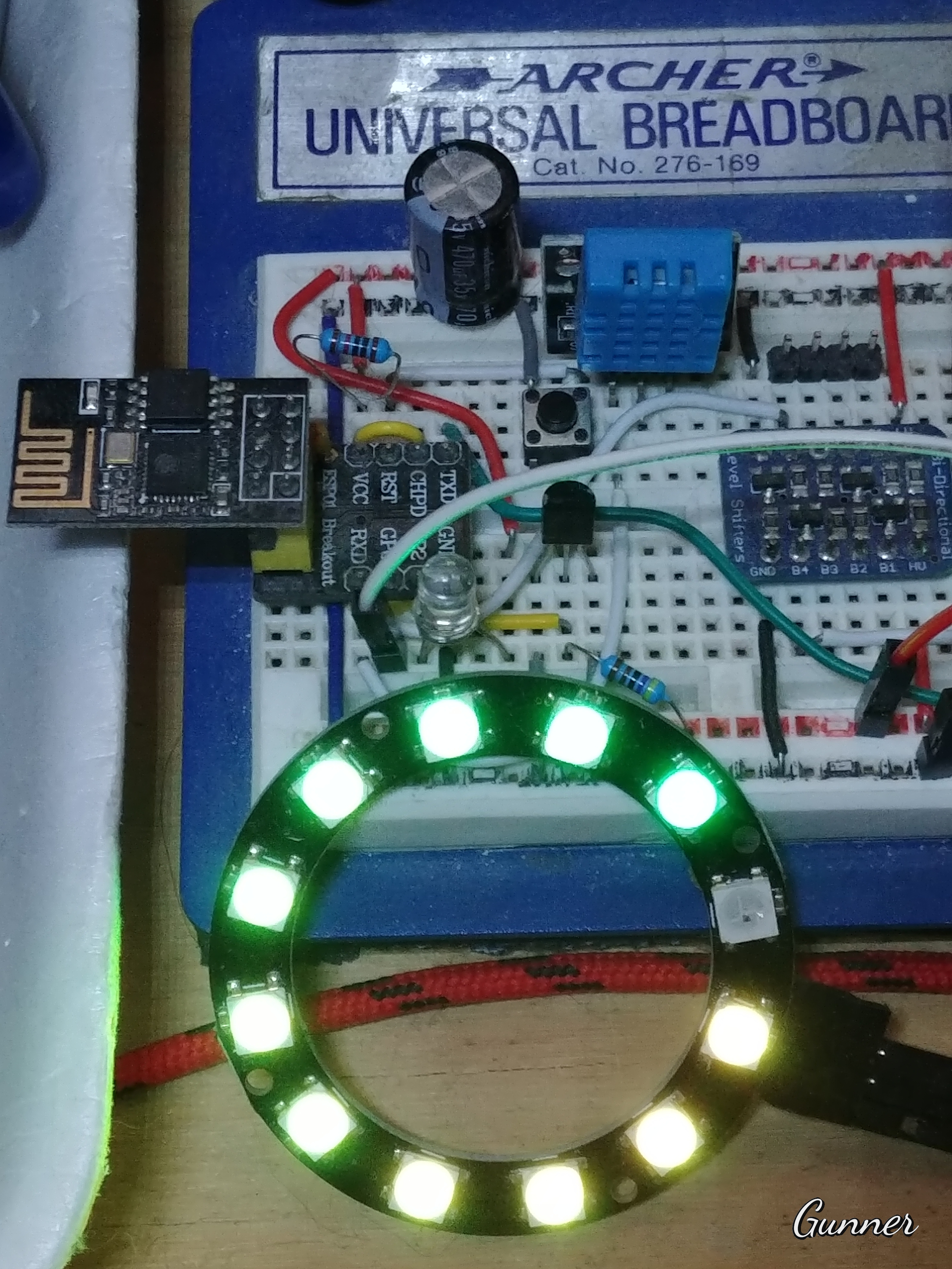
I have an ESP-01 running a DHT12 (GPIO3), a DS18B20 (GPIO2) and controlling a RGB LED Ring (GPIO0)… so a few more then just one pin usable.
I use OTA for any programming, but it is also wired for a TTL-USB adapter in case I goof up the OTA.
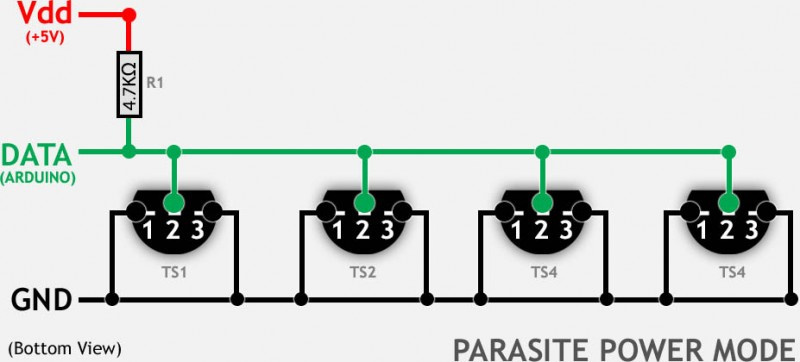
I use GPIO2 for my DS18B20 and I power mine via the parasitic method. My particular sensor wants the 5v line in order to function (@DoMoney - that might be your issue as well?) , but since it is feeding through a 4.7K resistor there is no concern.
void DS18B20TempSensor() { // DS18B20 sensor reading
  DS18B20.requestTemperatures();
  delay(500);  // Yes, I use a short delay... no problems in this case ;)
  Blynk.virtualWrite(V3, DS18B20.getTempCByIndex(0));
}
As a neat trick, I even have an LED (white - no resistor) across the data and 3.3v line… so it actually pulses quickly everytime the temperature is reading.
Yep, I actually have messed with GPIO1 as well… it is one pimped out ESP-01 . The sketch is set with pinMode(1, OUTPUT); and I have done sophisticated things (OK, just blinked another LED ) But as it is wired to my TTL socket, I don’t do anything permanently with it… besides, I am already overloading the PSU with the RGB Ring
Although looking at it closer I forgot I had downgraded to a DHT11… and a burnt out RGB… poor ESP
Hi, again.
One simple question due to the above code. I’m using the chat widget and getting the temperature in the following format:
35,500 C, 35.750 C, 36,000 C.
Due to the properties of chart fidget, I have set the format “#.#”, but it doesn’t work.
Can someone explain, is it bug of widget or not?
The DS18B20 does have a resolution of 2 decimal points… but providing you are running the latest App and the #.# range it (the SuperChart Widget as what I am assuming you meant ) should read just fine…
Again I have a problem.
I have changed the esp, as the last one was crashed.
I have esp-01, alsmost the same like it was (the only difference is the power led), but it doesn’t show me the temperature. The problem is in hardware. Can U help me:
Last configuration was the following:
VCC: 3,57 V
ground
GPIO0
The thermal sensor ds18b20 is connected by 3 wires and I have used 10kOhms resistor. All was working great.
New configuration is following:
everything is the same, but I have connected VCC with EN(CH_PD), because the esp didn’t start without it. But the temperature is showing -124.5.
The most interesting thing, if I’m putting esp-01 to usb to uart converter
(converter ) without putting it into the laptop, all is working fine. Can U explain to me, what I am doing wrong.
Thanks
I don’t understand what you are referring to here. Different power sources? Different way of programming? What is different?
And “all is working fine”… means what? That the temperature reading is correct when you are plugging into a programmer (TTL-USB)… but not actually powering or programming it (No USB connection)??
Thanks for your answer.
The difference is in power led of esp and that I have to connect CH_PD to VCC to start the esp. Power source is the same, the code is the same.
When I’m inserting the module into TTL-USB, the measurement is correct (TTL-USB module isn’t inserted anywhere). When I’m unplugging it, I’m receiving the temperature -124.5. Please advice.
The LED is just a manufacture thing… but probably an indication of one of the newer 1 Mb models. The CHPD (Chip Enable) should have ALWAYS needed 3.3v in any model that I have used.
I don’t quite understand the whole works with TTL-USB thing, as that it is only needed when flashing a sketch onto the ESP-01 anyhow (although I always use OTA for mine set with 1M no SPIFFS, after the initial flashing). But perhaps it is a power thing? The ESP-01 itself still needs a decent current capable PSU and maybe your TTL-USB adapter is supplying such. I recommend minimum 800mA to 1A
And if the extra current is not the answer, then your sensor may need a higher voltage than 3.3v. Mine requires 5v even in parasitic mode… I think it might be just the batch I purchased as they are supposed to work with either 3.3v or 5v
Look, regarding CHPD, at my previous esp-01, I didn’t need to connect the CHPD with VCC and all was working fine, in this version it doesn’t - so I have connected them.
Regarding the power, the problem isn’t at power, as all was working good with the prvious version of esp.
Regarding TTL-USB converter, I don’t plug it into computer, so the power is going from separate PSU directly to esp. TTL-USB converter is just in air. I beleive, it’s connecting some addition pins at esp and due to this, all is working good, when esp is inserted into converter.
Either it was damaged, or it was some special version I’m not aware of - Some additional pullup to VCC? Never seen such an ESP-01…
Now, because you are using GPIO0, which on the USB companion board MOST PROBABLY is pulled up with a resistor (10K?) AND you say it is working, THEN perhaps changing the 10k resistor you had connected to sensor with 4,7k or even 3,3k (better on longer line and 3,3V supply) will do the job??
I was simply pointing out what every diagram and even espressif themselves indicate in the datasheets - the Chip Enable Pin is active HIGH.
Different chip, probably the larger memory version as I stated before, possibly different power needs? Clearly something has changed, since it apparently doesn’t work now
There is only so many pins to work with… Your TTL-USB clearly changes something, so determine what and you may have your answer.
Change the pin used for the sensor, try both power delivery methods for the sensor (parasitic and direct), try both 3.3v & 5v for the sensor, try a different sensor… This is not something we can look over your shoulder about.

 . The sketch is set with
  ) But as it is wired to my TTL socket, I don’t do anything permanently with it… besides, I am already overloading the PSU with the RGB Ring

