#14 - ESP32 - Alternate way to control PWM pins for Servos and/or LEDs
At the time of this posting, the ESP32 Arduino Core does not support the handy analogWrite() command. So how do we do the PWM dodo we want to do?
Well, a little G  gling later and I found a few different websites that describe in more detail then I will get into here. How profoundly customisable the ESP32 GPIO pins are
First you need this library…
And here is just a couple of sites with usage examples…
-
http://www.instructables.com/id/Interfacing-Servo-Motor-With-ESP32/
-
https://techtutorialsx.com/2017/06/15/esp32-arduino-led-pwm-fading/
Basicly the GPIO pins can be linked to 16 independent channels, with configurable duty cycles and wave periods. The accuracy of the duty cycle can be configured up to 16 bits of resolution.
I am using 50Hz and 16-bits for the Servo control. for my servo 2000-8000 was a good range in the settings, without pushing the limits of the servo.
And for the RGB LED I am using 5000Hz but only 8-bits to give the range of 0-255 in the settings
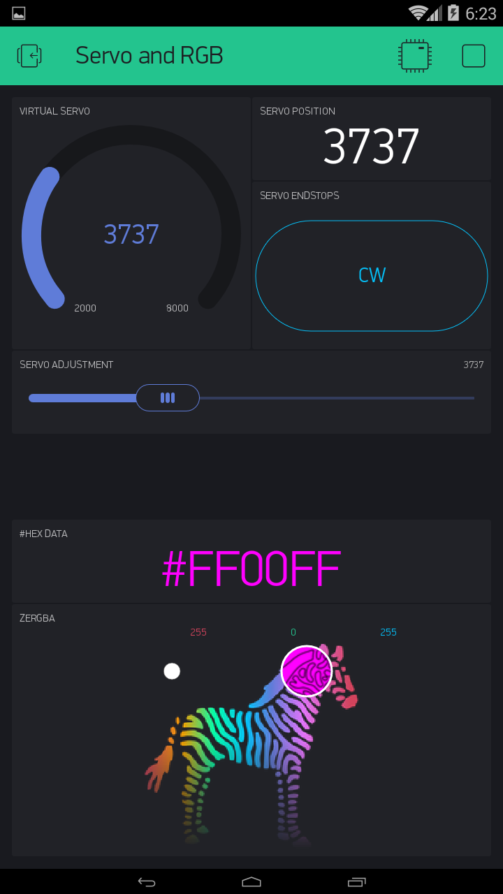
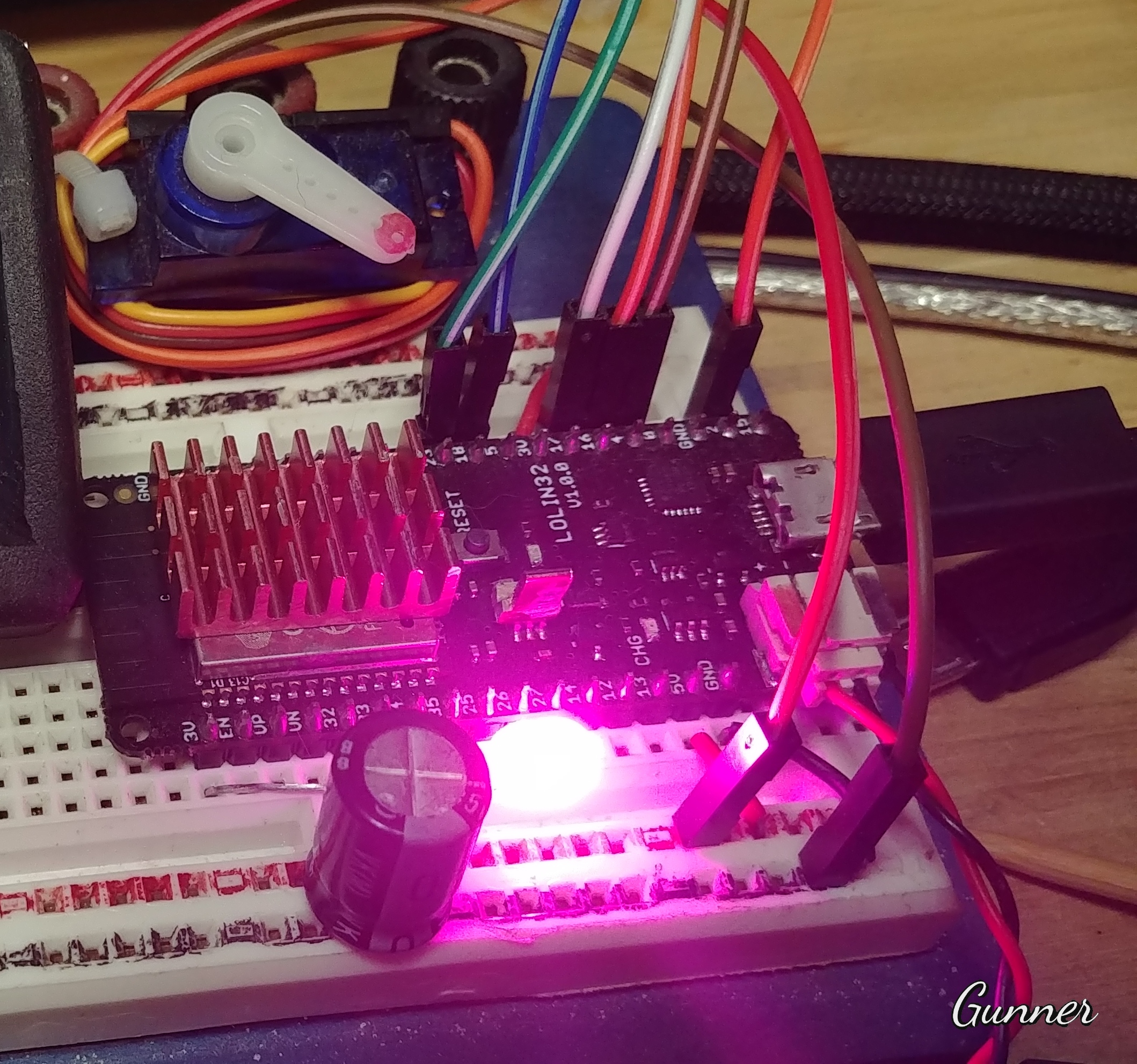
For those that like to visually see results right darn now!!.. here is a small project that you can use… and even if you don’t have a servo motor or a 4 lead RGB LED, you will see the results on the App (OK a Gauge Widget is a poor substitute for a Servo  but the HEX data that shows the corresponding colour is useful)

//#define BLYNK_PRINT Serial // This prints to Serial Monitor

#include <WiFi.h>
#include <WiFiClient.h>
#include <BlynkSimpleEsp32.h>

#include <ESPmDNS.h>  // For OTA - ESP32
#include <WiFiUdp.h>  // For OTA
#include <ArduinoOTA.h>  // For OTA

#include "esp32-hal-ledc.h" // For Servo & RGB PWM control

char auth[] = "xxxxxxxxxx";
char ssid[] = "xxxxxxxxxx";
char pass[] = "xxxxxxxxxx";
//char server[] = "xxx.xxx.xxx.xxx";  // IP for your Local Server
char server[] = "blynk-cloud.com";  // URL for Blynk Cloud Server
int port = 8080;

int rrr, ggg, bbb;  // Set RED BLUE GREEN channe
int ServoPos;


void setup() {
  //Serial.begin(115200);  // BLYNK_PRINT data

  //===== Servo pin setup for ESP32 =====
  ledcSetup(1, 50, 16); // For Servo - channel 1, 50 Hz, 16-bit width
  ledcAttachPin(2, 1);   // For Servo - GPIO 2 assigned to channel 1

  //===== RGB LED pin setup for ESP32 =====
  ledcSetup(2, 5000, 8); // For RGB-Red - channel 2, 5000 Hz, 8-bit width
  ledcAttachPin(25, 2);   // For RGB-Red - GPIO 25 assigned to channel 2

  ledcSetup(3, 5000, 8); // For RGB-Green - channel 3, 5000 Hz, 8-bit width
  ledcAttachPin(27, 3);   // For RGB-Green - GPIO 27 assigned to channel 3

  ledcSetup(4, 5000, 8); // For RGB-Blue - channel 4, 5000 Hz, 8-bit width
  ledcAttachPin(26, 4);   // For RGB-Blue - GPIO 26 assigned to channel 4


  WiFi.begin(ssid, pass);
  Blynk.config(auth, server, port);
  Blynk.connect();

  ArduinoOTA.setHostname("ESP32 Servo RGB");  // For OTA - Use your own device identifying name
  ArduinoOTA.begin();  // For OTA
}


//===== Servo Control Widgets =====
BLYNK_WRITE(V1) {  // Slider for selective servo positioning
  ServoPos = param.asInt();  // Get position data
  ledcWrite(1, ServoPos);  // Move servo to position
  Blynk.virtualWrite(V0, ServoPos);  // Display servo position
  Blynk.virtualWrite(V5, ServoPos);  // Show servo position
}  // END Blynk Function


BLYNK_WRITE(V2) {  // Button for servo endstop positioning
  ServoPos = param.asInt();  // Get position data (pre set in MIN/MAX settings
  ledcWrite(1, ServoPos);  // Move servo to position
  Blynk.virtualWrite(V0, ServoPos);  // Display servo position
  Blynk.virtualWrite(V5, ServoPos);  // Show servo position
  Blynk.virtualWrite(V1, ServoPos);  // Sync slider position
}  // END Blynk Function


//===== zeRGBa Widget =====
BLYNK_WRITE(V4) { // START Blynk Function
  rrr = param[0].asInt(); // get a RED channel value
  ggg = param[1].asInt(); // get a GREEN channel value
  bbb = param[2].asInt(); // get a BLUE channel value
  RGBprocess(); // Run Arduino funtion
}  // END Blynk Function


//===== Physical RGB LED Control and HEX conversion =====
void RGBprocess() {  // START Arduino funtion

  // For Common Anode+ RGB LED
  ledcWrite(2, 256 - rrr); // Write to RED RGB pin
  ledcWrite(3, 256 - ggg); // Write to GREEN RGB pin
  ledcWrite(4, 256 - bbb); // Write to BLUE RGB pin

  // For Common Cathode- RGB LED
  //  ledcWrite(2, rrr); // Write to RED RGB pin
  //  ledcWrite(3, ggg); // Write to GREEN RGB pin
  //  ledcWrite(4, bbb); // Write to BLUE RGB pin

  // zeRGBa pin to #HEX conversion
  String strRED = String(rrr, HEX);  // Convert RED DEC to HEX
  if (rrr < 16) {
    strRED = String("0" + strRED);  // Buffer with 0 if required
  }  // END if
  String strGRN = String(ggg, HEX);  // Convert GREEN DEC to HEX
  if (ggg < 16)  {
    strGRN = String("0" + strGRN);  // Buffer with 0 if required
  }  // END if
  String strBLU = String(bbb, HEX);  // Convert BLUE DEC to HEX
  if (bbb < 16)  {
    strBLU = String("0" + strBLU);  // Buffer with 0 if required
  }  // END if
  String HEXstring = String("#" + strRED + strGRN + strBLU);  // Combine HEX fragments
  HEXstring.toUpperCase();  // Change HEX value to all upper case for ease of visuals.
  Blynk.setProperty(V3, "color", HEXstring);  // Change background colour of HEX Data Label
  Blynk.virtualWrite(V3, HEXstring);  // Display HEX data
}  // END Arduino Function


void loop() {
  Blynk.run();
  ArduinoOTA.handle();  // For OTA
}