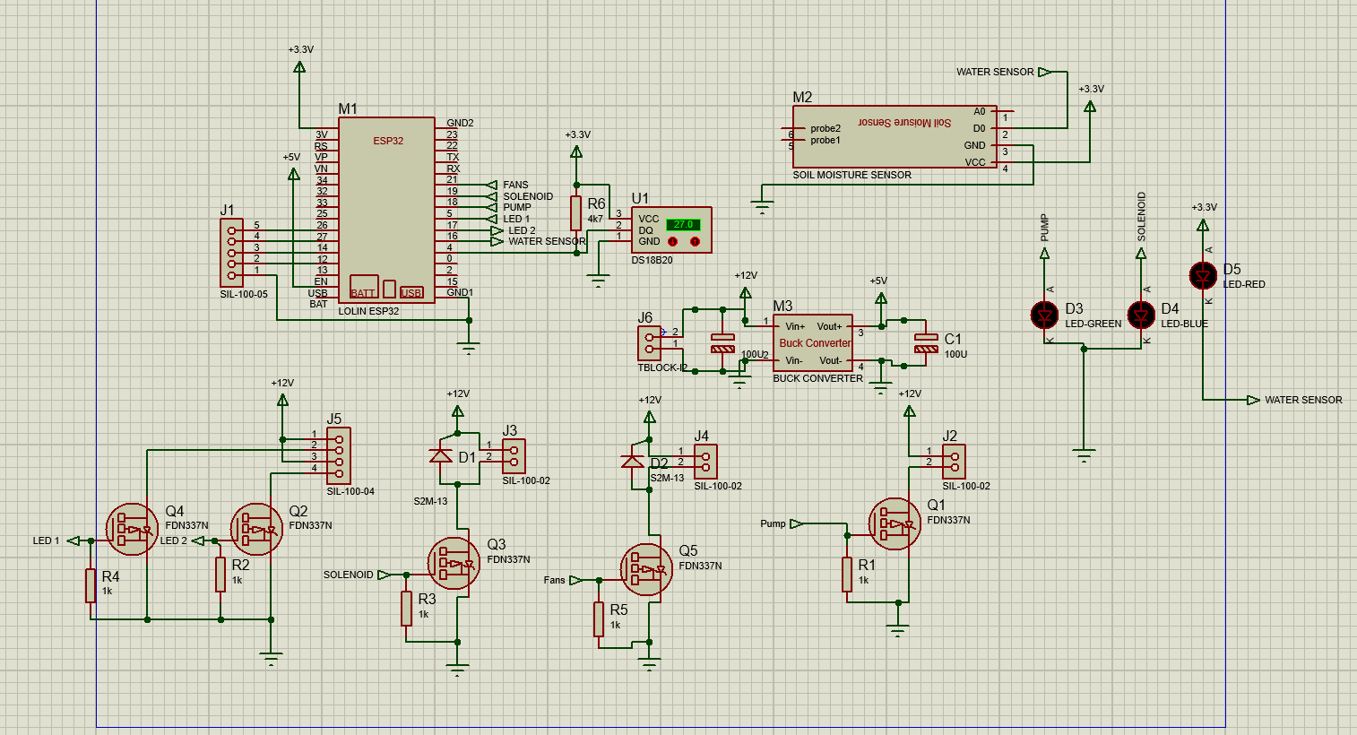
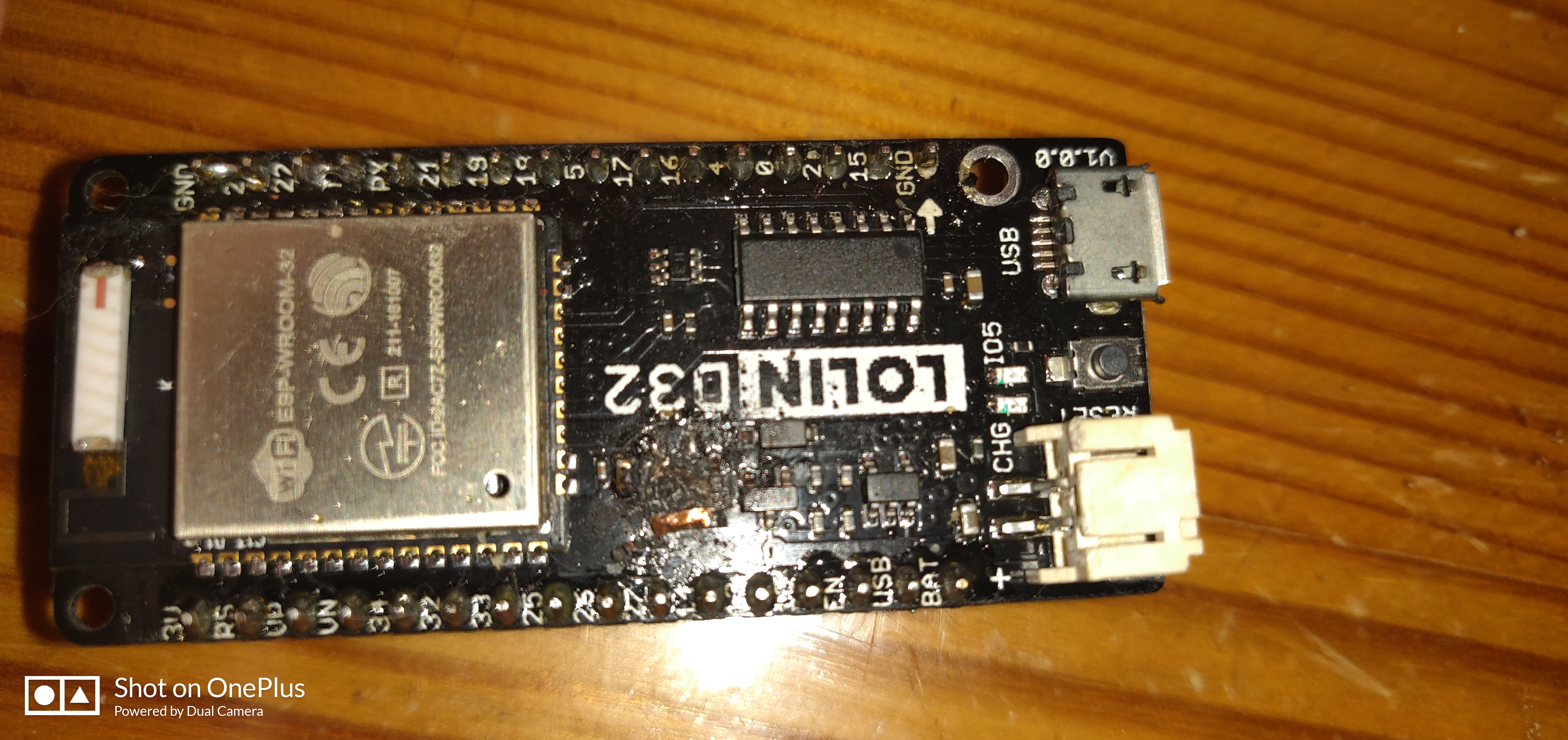
For this past few weeks I have been working on a project with a WEMOS ESP32 Board. In short the project is able to turn on and off some 12V led lights(according to RTC widget) and control a 240V Pump(via relay) and a small 12V Solenoid Valve. It also has 4 float sensors. So, everything worked on a breadboard and I design a PCB and ordered it from JLCPCB`s.
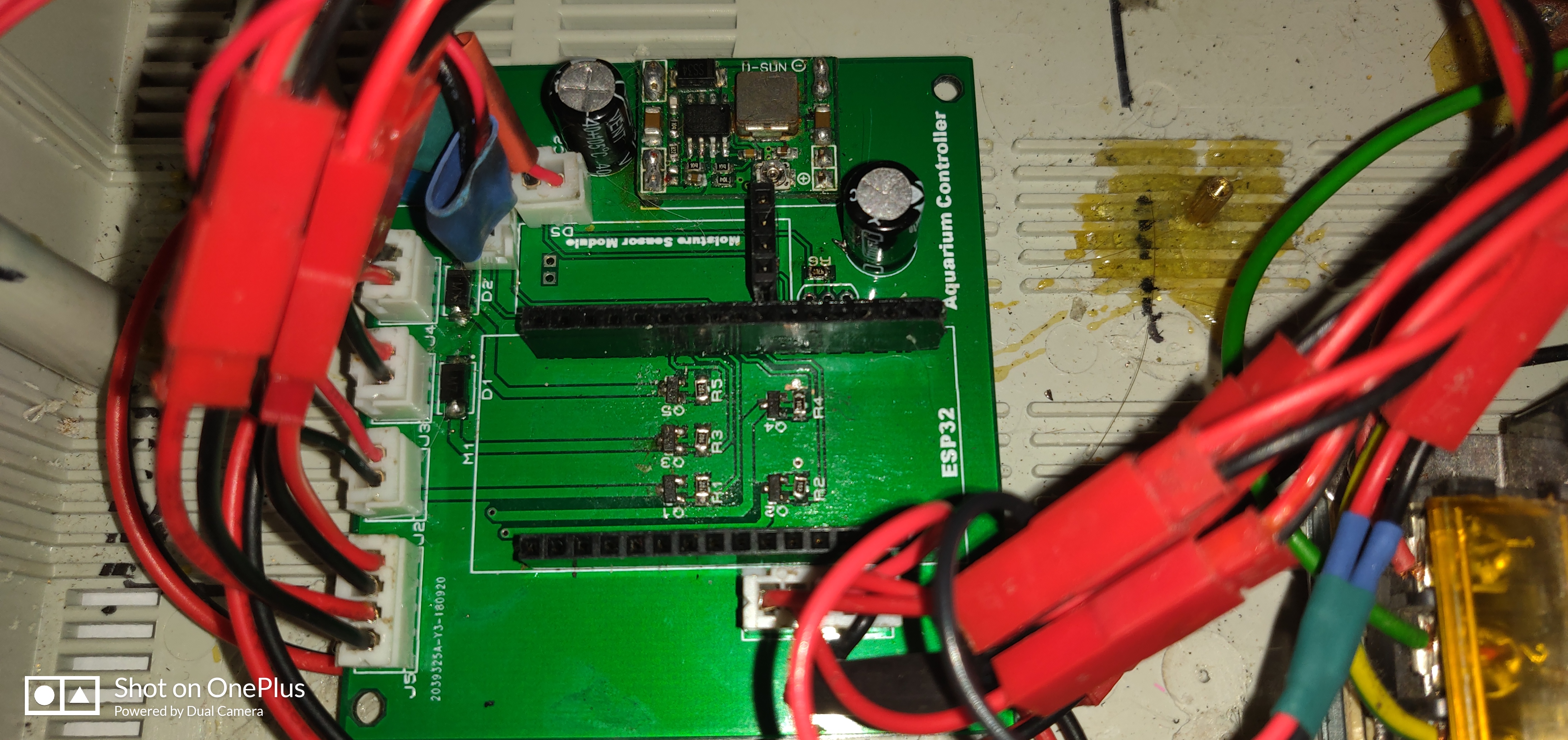
When it arrived I assembled it and everything worked fine until Today. Yesterday I received some 1K SMD resistors to act as pull-downs for the MOSFETS. After soldering them to the board I checked that everything worked and left it working overnight. This morning I left for work and when I came back at noon I noticed that the lights weren’t on.
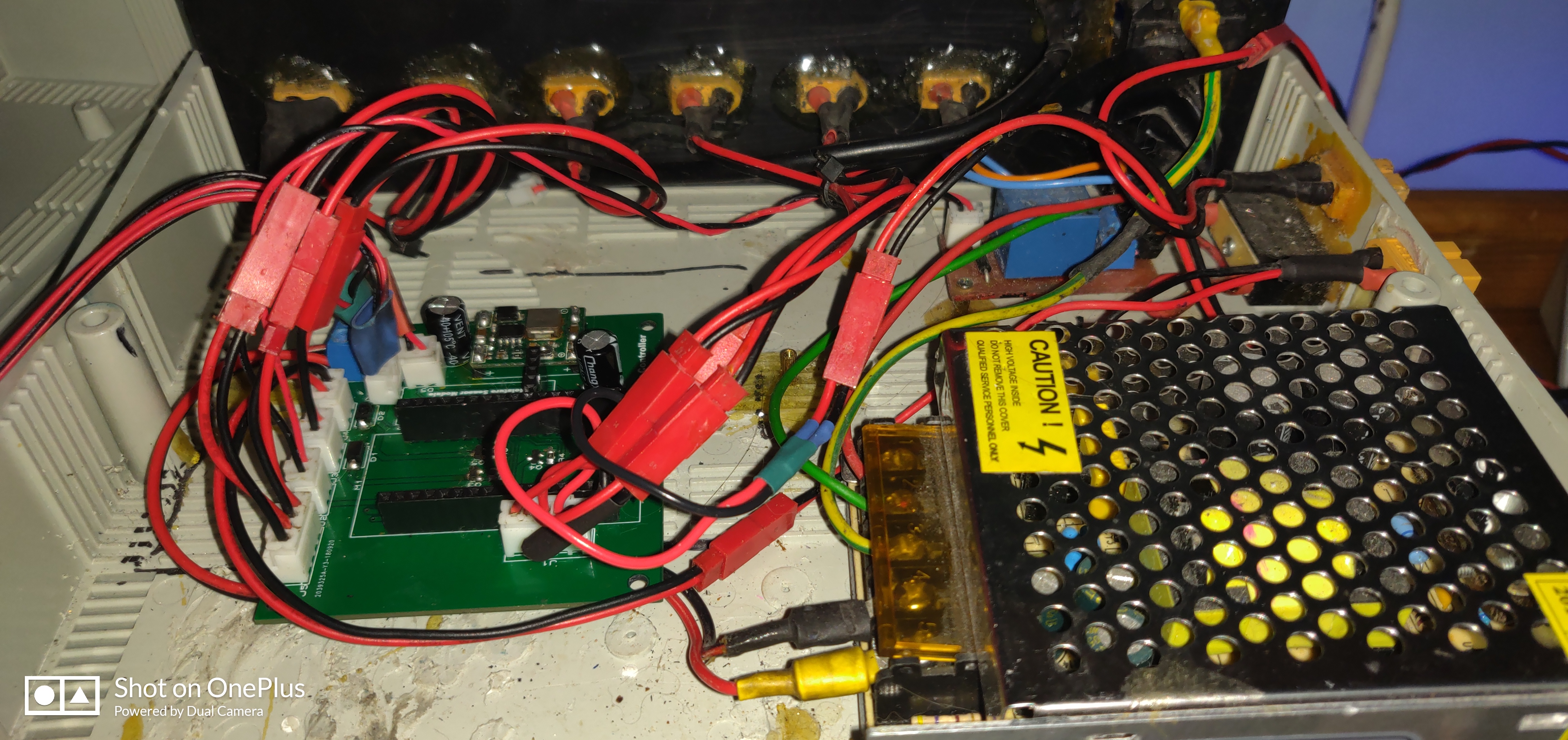
After checking my phone I noticed that the Project went offline at 2AM, 3hours after I soldered the resistors. When I checked what has happened I saw that my module was burnt. After checking which component it was I finally came to a conclusion that the Voltage Regulator went bad. I unplugged the esp module from the header pins and checked some voltages on the PCBS, Mainly on the base of the MOSFETS. I assumed that I had a short to ground but no. When measuring from base to ground I measured 1K Ohms across. Powering the ESP32 I had a Buck Converter stepping down from 12V to 5.2V. This voltage was hooked up to the USB pin on the board.
I cant understand why this happend and after 1 week of working perfectly fine? In that 1 week I didn’t experience any excessive heat. Upon further inspection I found the the MOSFETS still work if a voltage is applied to the base. Also I didn’t use it anymore after I checked if everything worked after soldering the resistors last night so none of the MOSFETS had to work at 2AM. (The lights turn on at 8 in the morning. I have attached the Schematic diagram of my PCB. Also I have ordered some new modules but I don`t want it to happen again.
I’m fairly certain that the 5v and 3.3v pins are meant to be input pins for the ESP range of dev boards.
By using the 3.3v pin as a supplyfor your circuit, you’re using the onboard voltage regulator to achieve the 3.3v output. This regulator is meant to be used to step down the 5v supply to power just the ESP chip, but you’re tapping-off some of this voltage to power some of your sensors.
While this works, and many people get away with it, I don’t think it’s the correct way to use these boards.
You’d be better-off adding a separate voltage regulator to step down either your 12v or 5v rails to 3.3v and powering your sensors from this rather than from the 3.3v pin on your ESP board.
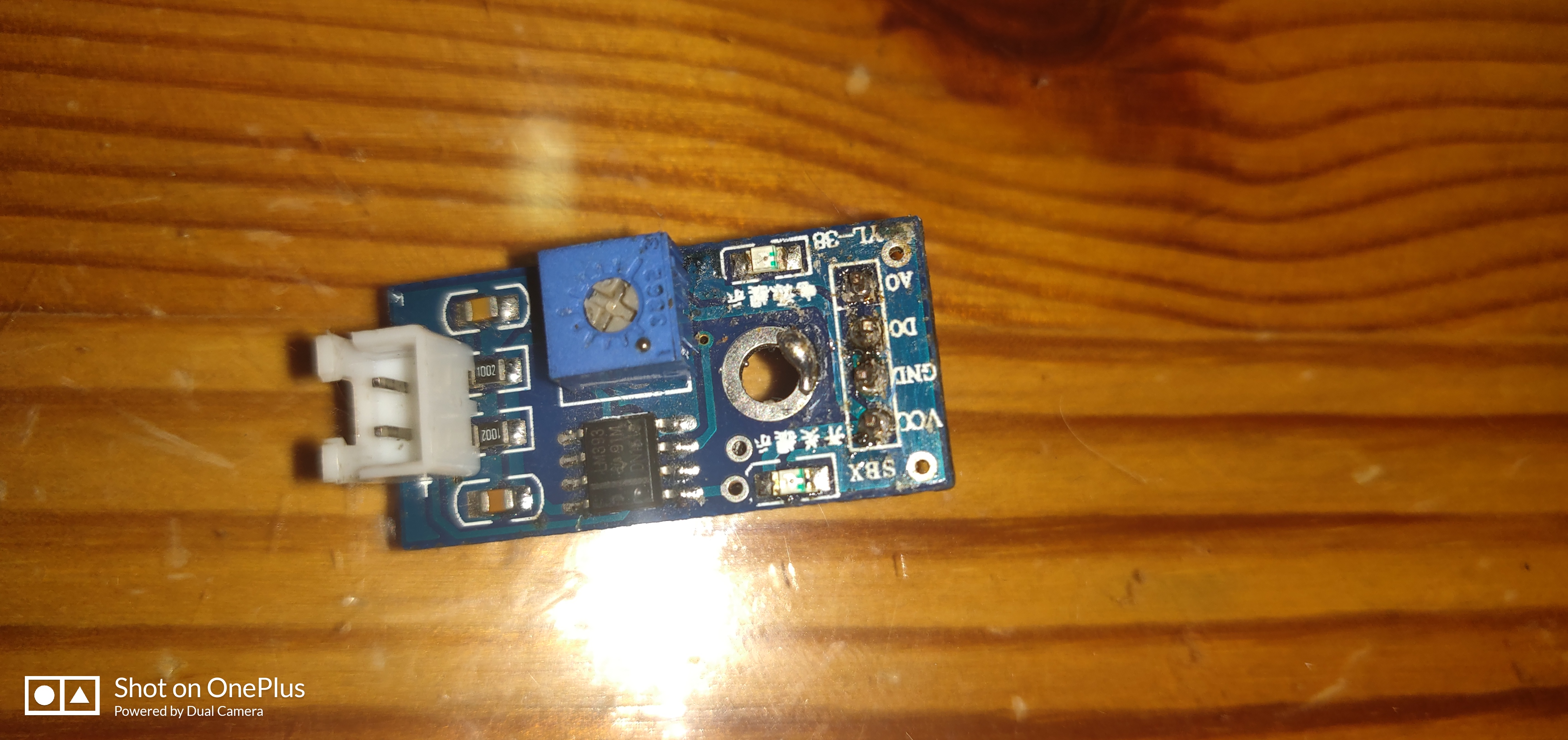
The only thing that is connected to the 3.3V Pin is a water detection module that is used when water is near the probes. It gives a HIGH signal normally and when water is detected it gives a low signal. Do you think that is the problem?
This is just a guess without digging into this too deeply… perhaps the addition of the pulldowns might have allowed a lower path of resistance for potential back voltage from the 12v through the MOSFETS to the ESP?
My guess is that ESP received too high input voltage from “faulty” voltage converter. I had similar issue (although different converter) and the potentiometer was just a little bit unstable and sometimes it just allowed full input voltage to flow directly to output. It is better to replace the pot with fixed resistors after setting and measuring the variable resistor.
The 1kohm resistors are connected correctly, although I would give them higher value (~3,3 - 4,7k). These are just to prevent the “floating” (high impedance) ESP output state.
JUST NOTED: Where are the current limiting resistors for your LEDS??? You can’t connect them directly, as you simply overloading ESP’s output pins!!
That could be a big possability. I will try replacing the pot with a fixed one. Should I lower the 5V coming out maybe closer to 3.3V so that the onboard Regulator is more efficient. Also the resistor are attached but are not shown in the photos. They are attached to the anode of the leds (not on the board).
You can lower the output voltage to about 3,8-4,0V. The LDO voltage regulator may have as little as 0,2V voltage dropout (I don’t know what type is used on ESP32 board) but I would certainly leave some margin.
As for the gate resistors: I usually put some 100ohm resistors in series, but rather when building “fast” (that’s always relative ) switching circuits to offload MOSFET’s drivers from high input capacitance of high power mosfets (especially when parallelized). Keep in mind, that placing a series resistor AND a pulldown connected to gate you are creating a voltage divider, which is undesired in case of such a low gate voltage (3,3V). Either place pulldown res before the series resistor,or abandon the latter.
Ok when I get the ESP32 boards I will set the voltage lower and see how it will go from there. On the board they use the ME 6211 Voltage Regulator.
One other question, In this circuit I used the FDN337N which can handle up to 2.2A at maximum. If I attach a higher current load which MOSFET should I use? I will need a MOSFET capable of at least 2.5A. If possible in the SOT-23 package. This also needs to be driven from an ESP32 Pin.
Note the rest of important parameters (Gate threshold voltage Max source-drain voltage…) The first on the list looks promising : AO3400A (current as high as 5,7A)
 ) switching circuits to offload MOSFET’s drivers from high input capacitance of high power mosfets (especially when parallelized). Keep in mind, that placing a series resistor AND a pulldown connected to gate you are creating a voltage divider, which is undesired in case of such a low gate voltage (3,3V). Either place pulldown res before the series resistor,or abandon the latter.