And… well… better programming layout… I am not following yours very well I am afraid. You have a timer that seems to watch your switch and send too many status updates every second… but that is all your program seems to do. Nothing ever calls the supposed relay function.
PS, this forum is really about teaching about Blynk, not general programming. Lots of sites out there for that. Find some examples, learn how they work, then look at adding in Blynk functionality.
The code in void program() is never getting called.
It’s a stand-alone piece of code which won’t run on its own, so your relay will never be activated.
how about the reed switch status part of the code, is that atleast making sense? I know it works on the blynk app but does the logic of the code and its flow make sense to your fresh eyes.
It’s not the way that I’d choose to write that bit of code, but them I’m a self-taught bodger.
These read switches can suffer from contact bounce, but it depends how often you poll the switch using the timer as to whether this will be an issue. You’re currently checking the switch every second, but this doesn’t seem very often. Is the read switch being used to sense the position of the door so that you know when to stop the motor running, or simply to sense if the door is open/closed. If it’s the latter then once per second (or even less frequently) should be fine. However, if it’s meant to act as a limit switch then you may not want to allow the motor to run for upto an additional second once it reaches the limit point.
my intent with the reed switch is only to check status. if i see while i am away that the door is open somehow i want to actuate via blynk through a relay to close the door.
i have modified the code to new one. Still the virtual led on the blynk app changes color to show the currently status of the door ( red color for door open and green color for door closed) but the relays do not actuate or click. the 2 channel relay were expensive so i bought two of 1 channel relay.
The wiring setup is as follow
reed switch is hooked up to D3 & gnd
Relay 1 is hooked up to D5, 5V & gnd
Relay 2 is hooked up to D6, 5V & gnd
Relay 1 and 2 are jumpered at the middle connection ( common)
Both relay have built in physical leds ( one green and other red…but are always on)
virtual led on blynk is working fine like i previously said
#define BLYNK_PRINT Serial
#include <ESP8266WiFi.h>
#include <BlynkSimpleEsp8266.h>
#include <SimpleTimer.h>

char auth[] = "";

char ssid[] = "PIKIN-2";
char pass[] = "";

WidgetLED led1(V1);

#define BLYNK_GREEN   "#23C48E"
#define BLYNK_RED       "#D3435C"


SimpleTimer timer;

void blinkLedWidget()

 {
 if (digitalRead(D3)) {

    led1.setColor(BLYNK_RED);  // magnetic switch is open, D3 is HIGH
    Serial.println("Door is open");

  } else {

    led1.setColor(BLYNK_GREEN);  // magnetic switch is closed, D3 is LOW
    Serial.println("Door is closed");

  }

}


void setup()
{
  // Debug console
  Serial.begin(9600);

  Blynk.begin(auth, ssid, pass);
  pinMode(D6, OUTPUT);   // connects to D1 of Relay
 pinMode(D5, OUTPUT);   // connects to D2 of Relay
  pinMode(D3, INPUT);    // connects to NC Magnetic Reed Switch


// Turn LED on, so colors are visible
  led1.on();
  timer.setInterval(1500L, blinkLedWidget);
}

void loop()
{
  Blynk.run();
  timer.run();
}
You still have pinMode() after Blynk.begin() which is a blocking command until connected… pinMode() should be first in setup as it can affect any devices connected to the pins at bootup.
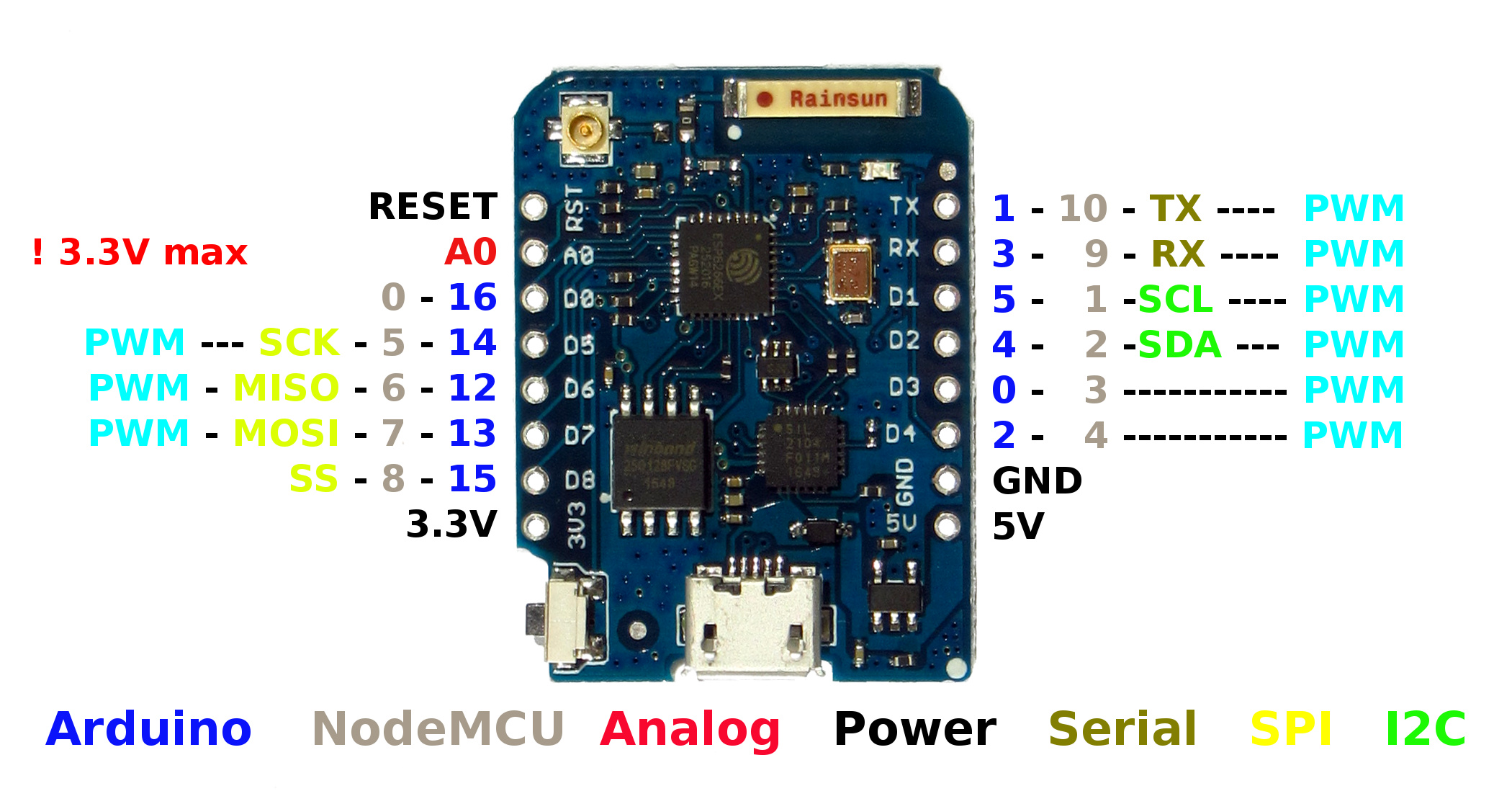
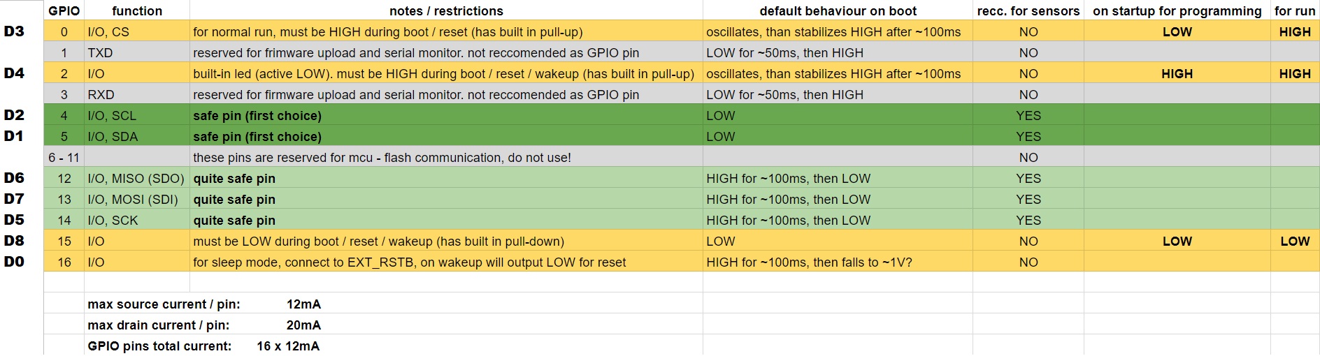
D3 (GPIO0) is probably not a good pin to use for your input… see this chart for optimal pins to use first.
There are no instructions here to activate the relays.
I’d expect to see something like this…
void blinkLedWidget()

 {
 if (digitalRead(D3)) {
    led1.setColor(BLYNK_RED);  // magnetic switch is open, D3 is HIGH
    digitalWrite(D5,HIGH);
    Serial.println("Door is open");

  } else {
    led1.setColor(BLYNK_GREEN);  // magnetic switch is closed, D3 is LOW
    digitalWrite(D6,LOW);
    Serial.println("Door is closed");
  }
}
It depends on whether your relays are active HIGH, or LOW, and how they are supposed to be triggered in relation to each other.
the only bit of instruction on it related to the relay was as follows " On the relay, the commons are connected with a jumper wire. The use the NO connection from D1 and NC connection from D2 to connect to the physical garage door opener. This way if the power is lost on the project, once power is restored, it will no cause the door to open. Also be sure to use the 5volt connection from the WeMos to provide power to the relay…it requires 5vdc and will not work with the 3.3v output."
@rav527 I think you were on the right track with the code in your first post. You just need to restructure your setup() as @Gunner had mentioned (put PinMode() before Blynk.begin() and the timer).
I think this potion of code should keep you from sending too many notifications (unless you are opening and closing your garage every 15 seconds) You could even add the virtual LED stuff to your IF statement.
Next is to think of how the current button opens/closes your garage door. Most (if not all) I have seen just require a short push of a button to open/close. So this is what you will want to simulate with your relay/code. Using the existing button on the wall for local control makes things easier as you wont need to add code for monitoring a button (if there currently isn’t one then we can address that next). So to open/close your garage from the BLYNK app you will need the button widget set to switch and set it up so that it send the HIGH signal when pressed as your relays are active HIGH. In the code you will just need to monitor the BLYNK Button and take appropriate action when pressed, this will include sending the high signal to the relay for a short duration (approx. .5 second) then sending the LOW signal to deactivate it (like pushing the button on the wall) and finally updating the status of the button widget. Here is a snipet of code that should do the above functions.
BLYNK_WRITE(V0) //Button Widget set to Virtual pin 0, set to switch
{
  int value = param.asInt(); // Get value as integer

  if (value == 1)
  {
     digitalWrite(13, HIGH); // Set GPIO 13 HIGH, relay ON
     timer.setTimeout(500L, []() {  // Run after 0.5 seconds second
          digitalWrite(13, LOW);  // Set  Pin 13 LOW, relay OFF
          Blynk.virtualWrite(V0, LOW);// Set  Virtual Pin 0 LOW
           });  // END Timer Function

}
As for wiring, just tap off the existing button. One wire to the common and the other to the normally open.
Hope this all makes sense, and is of some help. My BLYNK garage door monitor/opener was one of my first projects and I use it almost daily. It got me hooked. BLYNK ON my friend.
reed switch works correctly. the relay does not click.
the relay yellow light comes up as soon as i hook up 5v and gnd to it. The red light as well as click sound comes up as soon as the wemos board boots up. After that no matter how many times i press the button on the app, it does not do anything. both light stay on and thats about it.
none of that work. I tried removing the relay from the circuit and instead adding a led to the gpio that sending signal to relay and it lights up when i press the button on the app.
i have four of these relays and all are behaving same so dont think all the relays are defective also.
Well it sounds like the code is working (if it is flashing the LED when you press APP button), and I do not see anything wrong with the code. So it must be a hardware issue. Would you happen to have a link to the relays?
I will point this out again As por power can sometimes make relays click, but not properly work otherwise.
Also sounds like the relay is tripping (at least part way) into the Activated condition upon boot (may be Active LOW relays). reverse your pin logic so that instead of going HIGH when pressing button, it goes LOW.