I have been working on a project for a while now, using the insight of the more technical posts, but I finally got stuck.
Here is the gist of it; I need to make a ESP32 based product that has no connection to a computer. Currently, Blynk Edgent faults out the ESP32 if I do not have my ESP32 connected to my computer via USB. As soon as BlynkEdgent.begin(); is called in my setup() when the USB is not connected to the ESP32, the core faults out. Resetting the ESP32 does not change the behavior. Only reconnecting the ESP32 to the computer via USB allows the program to run. I have noticed this behavior in my complex program along with in the basic ESP32 example, Edgent_ESP32.ino available in the library examples. How can either prevent Blynk from trying to check for a serial connection, create a ‘fake’ serial port to direct Blynk to use that does not crash Blynk, or otherwise keep Blynk from faulting out when there is no serial connection?
Here is my setup:
Hardware: ESP32 WROOM 32D (see link)
Comms: WIFI
Phone OS: Android
Blynk Server
Blynk Library v1.0.1
Here is the example code with some modifications, including a custom hardware definition and the serial setup and debug lines commented out. No other changes were made.
// Fill-in information from your Blynk Template here
#define BLYNK_TEMPLATE_ID "TMPLSCX6s5xg"
#define BLYNK_DEVICE_NAME "5002FFProto"

#define BLYNK_FIRMWARE_VERSION        "0.1.0"

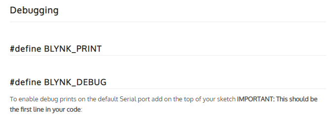
#define BLYNK_PRINT Serial
//#define BLYNK_DEBUG

//#define APP_DEBUG

// Uncomment your board, or configure a custom board in Settings.h
//#define USE_WROVER_BOARD
//#define USE_TTGO_T7
//#define USE_ESP32C3_DEV_MODULE
//#define USE_ESP32S2_DEV_KIT
#define ESP32FF_BOARD

#include "BlynkEdgent.h"

void setup()
{
  //Serial.begin(115200);
  delay(100);

  BlynkEdgent.begin();
}

void loop() {
  BlynkEdgent.run();
}
And the custom board definition in Settings.h for reference, which was placed before the #else for a custom board definition. This just ports the LED to an external LED I have on my breadboard, along with an external button.
///////////////////////////////////////////////////////////////////////////////////////////////////////////

// EDITED 2/15/2022 2:23PM NS

// CUSTOM BOARD FOR FF IOT PROJECT #5002

#elif defined(ESP32FF_BOARD)


  #define BOARD_BUTTON_PIN            15

  #define BOARD_BUTTON_ACTIVE_LOW     true

  #define BOARD_LED_PIN               17

  #define BOARD_LED_INVERSE           false

  #define BOARD_LED_BRIGHTNESS        255

////////////////////////////////////////////////////////////////////////////////////////////////////////////
From what I have read on other topics, it seems like there has been a lot of work done to try and port BLYNK_PRINT to use other means of displaying debug and crash reports, but nothing that fully describes what alternatives to ‘Serial’ that can be used for BLYNK_PRINT. The threads linked below have such applications, like the terminal in the Blynk app and also a LCD screen, both of which could be options for me I suppose. Credit to @Gunner and @Costas for your work there. I’ll link them in a reply to this, as the forum will not allow me to include them in this original post.
And yes, I even consulted the ancient texts, but the new and old documentation leaves a sour taste in my mouth…

Gotta love an empty entry… docs.blynk.cc/#blynk-firmware-debugging-define-blynk_print
Any ideas or ways to consolidate the Terminal and LCD means into a single topic that covers all the possibilities? I’ve gotten lost in the source code trying to find what alternatives the firmware will accept. It appears that the old version of Blynk readily supports commenting out BLYNK_PRINT, as shown below, but not the new verison. This was sourced from the Blynk example generator, which appears to be setup for the old version of Blynk.
/*************************************************************

  You’ll need:
   - Blynk IoT app (download from App Store or Google Play)
   - ESP32 board
   - Decide how to connect to Blynk
     (USB, Ethernet, Wi-Fi, Bluetooth, ...)

  There is a bunch of great example sketches included to show you how to get
  started. Think of them as LEGO bricks  and combine them as you wish.
  For example, take the Ethernet Shield sketch and combine it with the
  Servo example, or choose a USB sketch and add a code from SendData
  example.
 *************************************************************/

// Template ID, Device Name and Auth Token are provided by the Blynk.Cloud
// See the Device Info tab, or Template settings
#define BLYNK_TEMPLATE_ID           "TMPLxxxxxx"
#define BLYNK_DEVICE_NAME           "Device"
#define BLYNK_AUTH_TOKEN            "YourAuthToken"


// Comment this out to disable prints and save space
#define BLYNK_PRINT Serial
Thanks in advance.