Доброго всім вечора,
Стикнувся з проблемкою синхронізації цифрових pin-ів ардуіно через node-red.
Підкажіть яким чином можна направляти msg.*** через node-red в blynk?
Доброго всім вечора,
Стикнувся з проблемкою синхронізації цифрових pin-ів ардуіно через node-red.
Підкажіть яким чином можна направляти msg.*** через node-red в blynk?
Hi,
Apologies for replying in English.
To control a digital pin with Node-Red you should run MQTT client software on your Arduino, connect to your MQTT server and subscribe to an MQTT topic.
You can then send MQTT messages from Node-Red to your Arduino and use Arduino code to write to your digital pins based on the content of the message.
Pete.
Hey there my friend!
I`m using “https://www.npmjs.com/package/node-red-contrib-blynk-ws” this contrib to acces to my arduino-blynk but its only sends me a payload to a virtual pins not to digital.I need to send a payload (exmpl ‘1’ or ‘0’ to my relay on digital pin 2(D2 on my WeMos)
Hi,
Here is how I do it…
//Example of how to control a relay connected to GPIO5 (Wemos pin D1) using MQTT
// Change your Wi-Fi credentials on lines 17 & 18
// Change your Network details on lines 19, 20 & 21
// Change your MQTT server IP address on line 23
// Change your MQTT username and password on line 116

// Send MQTT message og 1 or 0 to topic MQTT/Example/Power to turn the relay on and off

// Add support for OTA***************************************
#include <ArduinoOTA.h>
// **********************************************************
#include <ESP8266WiFi.h>
#include <PubSubClient.h>

#define RELAY1     5      // Active HIGH Relay connected to GPIO5 (Pin D1 on Wemos D1 Mini)

const char *ssid =      "xxxxxxxx";
const char *pass =      "xxxxxxxx";
IPAddress ip            (192,168,1,xxx);          // Static IP Address for the device, Change to suit your network
IPAddress gateway       (192,168,1,1);
IPAddress subnet        (255,255,255,0);

IPAddress MQTTserver    (192, 168, 1, xxx);        // IP Address for the MQTT Server, Change to suit your network...

String POWERString;
int POWER =0;


WiFiClient MQTTWIFIClient;
PubSubClient MQTTclient(MQTTWIFIClient);


void setup()
{
  // Add support for OTA***************************************
  ArduinoOTA.onError([](ota_error_t error) { ESP.restart(); });
  ArduinoOTA.setHostname("MQTT Example");
  ArduinoOTA.begin();  /* setup the OTA server */
  // **********************************************************

  Serial.begin(74880);

  pinMode(RELAY1, OUTPUT);

  WifiConnect();

  MQTTclient.setServer(MQTTserver, 1883);
  MQTTclient.setCallback(MQTTcallback);


  digitalWrite(RELAY1, LOW);

} // End of void setup


void loop()
{
  // Add support for OTA***************************************
  ArduinoOTA.handle();
  // **********************************************************

  if(WiFi.status() != WL_CONNECTED)
  {
    WifiConnect();
  }

  if (!MQTTclient.connected())
  {
    MQTTreconnect();
  }
  MQTTclient.loop();

} // End of void loop


void MQTTcallback(char* topic, byte* payload, unsigned int length)
{
  Serial.print("Message arrived [");
  Serial.print(topic);
  Serial.print("] [");

  for (int i=0;i<length;i++)
  {
    Serial.print((char)payload[i]);
  }
  Serial.println("]");

  String mytopic = String((char *)topic);

  if (mytopic=="MQTT/Example/Power")
  {
    POWERString = String((char *)payload);
    POWERString.remove(length);
    POWER = POWERString.toInt();

    if (POWER==0) // If this was a Power Off instruction (0) then turn off the relay
    {
      digitalWrite(RELAY1, LOW);
      return;
    }

    if (POWER==1) // If this was a Power On (1) then turn on the relay
    {
      digitalWrite(RELAY1, HIGH);
      return;
    }
  }
} // End of void MQTTcallback


void MQTTreconnect() {
  // Loop until we're reconnected
  while (!MQTTclient.connected()) {
    Serial.print("Attempting MQTT connection...");
    // Attempt to connect
    if (MQTTclient.connect("MQTT_Example", "MQTT_Username", "MQTT_Password"))     // You cant have more than one device with the same ID (MQTT_Example). Replace MQTT_Username and MQTT_Password with your own
    {
      Serial.println("MQTT connected");
      // Once connected, publish an announcement...
      MQTTclient.publish("MQTT/Example/Output","Controller Alive");
      // ... and resubscribe
      MQTTclient.subscribe("MQTT/Example/Power");
    }
    else
    {
      Serial.print("failed, rc=");
      Serial.print(MQTTclient.state());
      Serial.println(" try again in 1 second");
      //Wait 1 second before retrying
      delay(1000);
    }
  }
} // End of void MQTTreconnect


void WifiConnect()
{
  WiFi.begin(ssid, pass);
  WiFi.config(ip, gateway, subnet);
  WiFi.mode(WIFI_STA);  // This only needs to be run once on each MCU, after that the line can be deleted, but there's no harm leaving it in here

  while (WiFi.status() != WL_CONNECTED)
  {
    delay(500);
    Serial.print(".");
  }
  Serial.println("WiFi connected");
} // End of void WiFiConnect
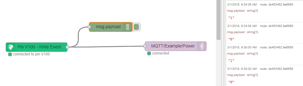
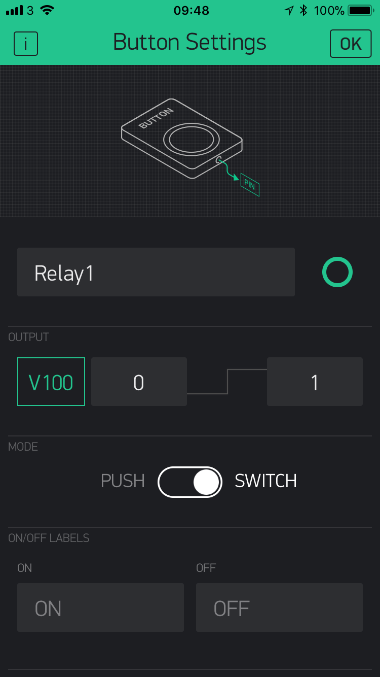
Pressing the button widget in the Blynk App sends a “1” to Node-Red, which is then sent by MQTT message to the Wemos. The code running on the Wemos listens for this message and turns the relay on.
Pin D2 on the Wemos is not GPIO2, it’s GPIO4. My code uses pin D1 on the Wemos, which is GPIO5, but it can easily be changed if you wish.
Pete.
Thx for reply,
I`ll try it later and give a feedback.Seems like it shoud work.Before I decide to do reverse way)