Strange things happen with the setup Blynk, MKR1000 and sensors.
The script is working well, I can see the readings on the Blynk App from the DHT11 sensor, but only when it is connected to USB, computer or external power bank. I ordered 2 lipo battery’s because the MKR1000 should work with them, even load etc.
But when I disconnect the USB cable, so it can run from the (full) LiPo battery, the readings stop. The MKR1000 stays connected to Blynk and that’s it, it hangs on the last readings where I disconnected the USB plug.
Have two MKR1000 boards and it is with both of them.
Did a search and the only this I found is that it could hang on a while(serial) command. But that is not in my code.
It might also be worth checking the voltage on the Vcc pin of the DHT11 to check that it’s getting at least 3.5v.
I assume that you don’t have any pullup/down resistors connected anywhere?
No Pete I have not. Checked everything, wiring, code, etc. It’s just very strange that it is with both MKR1000 boards and the LiPo’s. Tested two projects with other token numbers, they both do fine until I unplug the USB cable. They both stay online, I can see that in the App, but the measuring stops.
For the sketch I use the code generated by Blynk for MKR1000, Arduino wifi shield 101 (build-in) and DHT11. Nothing more, nothing less, just copy paste , and fill in the token ssid en pswd. All the necessary library’s are installed.
No problem to go online, just a great problem to get the measurements with unplugged USB port.
I have ESP32s with LiPo battery option… and yes, when unplugged from USB, certain devices don’t work as expected if they are assuming USB power (AKA 5v). Some sensors just don’t work well with the lower 3.3v… even if the specs claim it to be supported.
One way to test (guessing since you have no visible code to see ) is placing other indicators in the senor functions to indicate that they are still polling the sensor, etc… perhaps an LED that flashes on and off before and after sensor reading.
OK, I just upload a sketch without any sensors attached to the MKR1000, pluged in the LiPo battery and removed the USB cable. Result => it works ! So the final point is that the MKR1000 with lipo can handle the sketches with no sensors attached. If you try a sensor that even works on 3.3V the power from the LiPo to the board is not enough. THANKS GTT for the solution. Now I have to figure it out how I can feed the sensors with 5V and connect them in a safe way to the pins of the MKR1000 board (3.3v)…
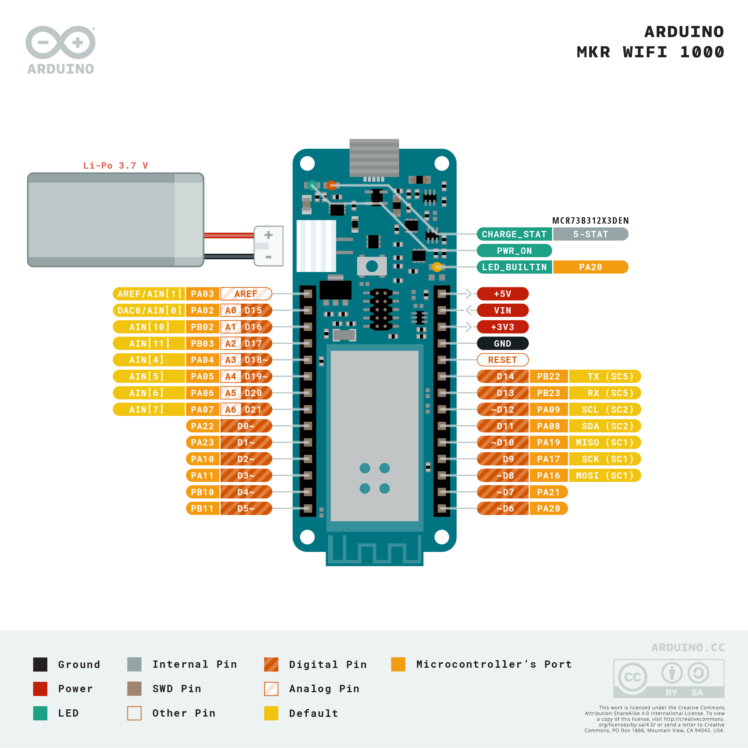
What pin on your MKR1000 is connected to VCC on your DHT11 ?
I suspect (and a wiring diagram may confirm this, but I can’t be bothered to look ) that the +5V pin (top right in this diagram) is connected to the 5v supply from the USB port. This will then go into the voltage regulator and 3.3v will appear on the +3V3 pin (third down on the right)
I assume that if there is no 5V supply from the USB then there will be no voltage on the +5V pin, but I’d still expect power on the +3V3 pin when its powered from the battery.
Your diagnose is complete correct ! I noticed that the pin on the breadboard was in the 5V on the MKR1000. I moved it to the VCC pin and everything works like sharm, even when I remove the USB connection. Then the LiPo battery take’s over the feed for the board. I am sorry for my mistake, but thanks to you I am back in business ! Great work Pete, and many thanks
Hello!
Im having some similar issues with my mkr 1400 gsm board, even with a fully charged 1s2p lipo it will not last more than a few hours. im going to try with a bigger pack. but is it safe to power the board with 5V on the VCC pin? if i run 5V on VIN it will not run.
 ) is placing other indicators in the senor functions to indicate that they are still polling the sensor, etc… perhaps an LED that flashes on and off before and after sensor reading.
 ) that the +5V pin (top right in this diagram) is connected to the 5v supply from the USB port. This will then go into the voltage regulator and 3.3v will appear on the +3V3 pin (third down on the right)