Hello everyone !
It seems that I might be in need of your aid a second time folks ! <3
I will be as precise as possible with my problem. I hope I won’t frustrate you. 
I made a Smart Light Switch project for my room using Blynk on an ESP8266 (ESP-01).
I’ve encountered several difficulties both on coding and on the hardware side, but after some reasearch I got to a good point.
I found help through these two pages:
Relay Connection with ESP-01
Physical Buttons alongside Blynk
> THE GENERAL PROJECT IDEA:
- I want to be able to control two separate lights in my room via Wi-Fi using Blynk.
- I also want to be able to control them via physical button in case my Wi-Fi goes off-line.
> WHERE I AM SO FAR
I’ve built a prototype on a breadboard guided by the links above.
I am using an ESP-01, a Low-Level Relay Board (pull to ground to activate) and a Capacitive Button as the off-line fail-safe. The button outputs HIGH when pressed.
I am using (according to the suggestion on the link) NPN Transistors to “drive” the Inputs of the Relay board. Acoording to the schematic I’ll post bellow.
I am using two Virtual Pins that control the two Separate Lights independently through the BLYNK app, and they cycle through OFF, 1ST_ON, BOTH_ON when using the physical button.
> DOES IT ACTUALLY WORK ? (The Problem)
-
When I boot the device up, it works flawlessly. I can control (as intended) the lights both from the APP and the Button.
-
Even if I disconnect the device from the Wi-Fi by turning off the Router, it works via the Physical Button.
-
The problem is, that IF I leave both lights ON (so both relays active) then after a couple of minutes, the device appears to shutdown. The Lights turn off, and my app says that the device disconnected.
If I quickly reset the ESP8266 it goes back up to normal.
-
IF I leave just ONE light (one relay) ON, then the device works as intended without disconnecting or shutting down, at least for the last 5 hours I’m testing it. It doesn’t matter which light (which relay, therefore which GPIO) I leave ON. It just has to be ONE of the two. Once I activate both at once, I got a couple of minutes before it shuts down.
-
When it shuts down alone, it appears to reset and restart on normal operation after some time. But then again shuts down and disconnects again.
> QUESTION TIME
- Is it possible that my ESP-01 is UNABLE to drive that much current and shuts off to protect itself ?
- Or maybe I’m not powering it with enough Milliamps ?
- Do you suggest any other Transistor / Resistor Configuration that would possibly solve the problem ?
Thanks a LOT in advance and sorry for taking your time. <3
(Did not fit in one post)
This is the Code I’m using:
#define BLYNK_PRINT Serial
#include <ESP8266WiFi.h>
#include <BlynkSimpleEsp8266.h>

char auth[] = "xXxXxXxXx";
char ssid[] = "xxxx";
char pass[] = "xxxx";
const int btnPin = 3;
const int Relay1Pin = 0, Relay2Pin = 2;
int state = 1;

BlynkTimer timer;
void checkPhysicalButton();

int btnPinState = LOW;
int RelayPinState = HIGH;
#define TURN_ON 0
#define TURN_OFF 1

void setup()
{
  Serial.begin (9600);
  Blynk.begin(auth, ssid, pass, "139.59.206.133", 8080);
  pinMode(Relay1Pin, OUTPUT);
  pinMode(Relay2Pin, OUTPUT);
  pinMode(btnPin, INPUT);
  digitalWrite(Relay1Pin, TURN_OFF);
  digitalWrite(Relay2Pin, TURN_OFF);
  timer.setInterval(100L, checkPhysicalButton);
}

BLYNK_CONNECTED(){
  Blynk.syncVirtual(V1);
  Blynk.syncVirtual(V2);
}

BLYNK_WRITE(V1){
  RelayPinState = param.asInt();
  digitalWrite(Relay1Pin, RelayPinState);
}

BLYNK_WRITE(V2){
  RelayPinState = param.asInt();
  digitalWrite(Relay2Pin, RelayPinState);
}

void checkPhysicalButton()
{
  if (digitalRead(btnPin) == HIGH)
  {
    if (btnPinState != LOW)
    {
  switch (state) {
  case 0:
    digitalWrite(Relay1Pin, HIGH);
    digitalWrite(Relay2Pin, HIGH);
    Blynk.virtualWrite(V1, RelayPinState);
    Blynk.virtualWrite(V2, RelayPinState);
    state = 1;
    break;
  case 1:
    digitalWrite(Relay1Pin, HIGH);
    digitalWrite(Relay2Pin, LOW);
    Blynk.virtualWrite(V1, RelayPinState);
    Blynk.virtualWrite(V2, !RelayPinState);
    state = 2;
    break;
  case 2:
    digitalWrite(Relay1Pin, LOW);
    digitalWrite(Relay2Pin, LOW);
    Blynk.virtualWrite(V1, !RelayPinState);
    Blynk.virtualWrite(V2, !RelayPinState);
    state = 0;
    break;
  default:
    digitalWrite(Relay1Pin, HIGH);
    digitalWrite(Relay2Pin, HIGH);
    Blynk.virtualWrite(V1, RelayPinState);
    Blynk.virtualWrite(V2, RelayPinState);
    state = 0;
    break;
  }
}
    btnPinState = LOW;
}
  else
  {
    btnPinState = HIGH;
  }
}

void loop()
{
  Blynk.run();
  timer.run();
}
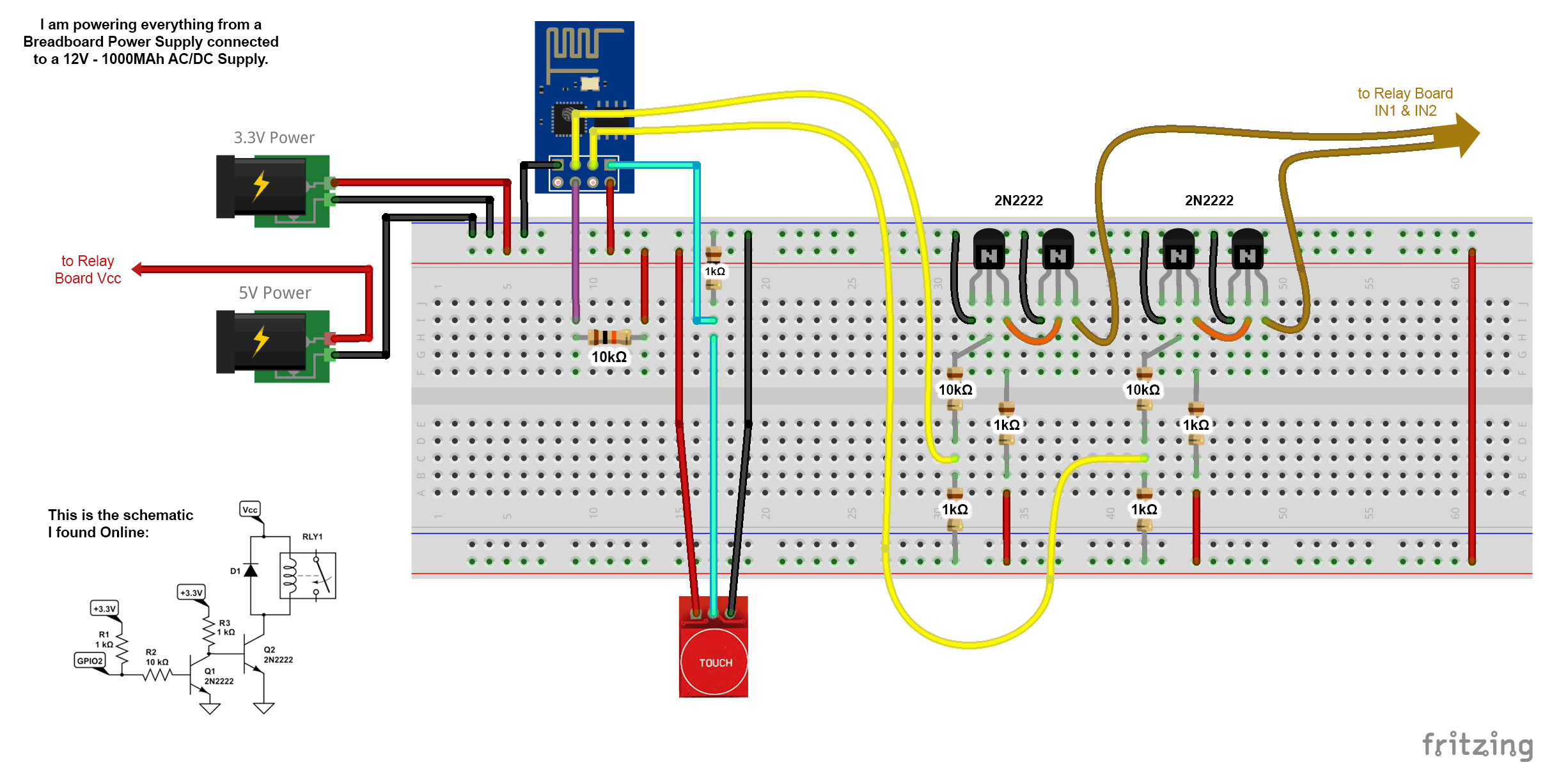
And this is the schematic I made for you, to better understand the Hardware Side:
If you’re using a relay board, which I assume you are from your description and reference to pins IN1 and IN2, then your ESP-01 should easily be able to drive it without the transistors.
The relay boards I use draw less than 1mA at 5v (around 1.5mA at 3.3v) from the actual GPIO pin that is doing the logic-level switching. The ESP-01 is good for 12mA per pin and 20Ma in total, so driving a couple of relays will be fine.
The article you linked to was about using a simple relay rather than a pre-built relay board. If you look at the relay board you’ll see that it has transistors, diodes and probably opto-isolators for each channel. These do what your transistors are doing.
I’m a bit confused about why you have a 10K resistor between the 3.3v rail and the CH_PD pin. Normally CH_PD would be tied directly to 3.3v without any resistor.
The statement that “I am powering everything from a breadboard power supply” rings a few alarm bells. These generally aren’t the best designed devices and aren’t usually designed to provide much current. It may be that the PSU cant sustain an output current on the 5V rail that is sufficient to keep the two relay coils energised for long periods of time.
Also, if you want to use the Tx pin (GPIO1) at any point in future then you need to remove the Serial.begin (9600); and #define BLYNK_PRINT Serial commands from your code.
GPIO1 may be a better pin to use than GPO0, as pulling GPIO0 LOW at startup will put the ESP into programing mode and this will prevent your code from executing.
Going forward, you would be much better off using a NodeMCU or a Wemos D1 Mini (or even an ESP-32) as these give you a lot more pins to play with and are much easier to connect-up, program and debug because of the onboard USB port.
Pete.
1 Like
Hello Pete.
Thnak you for your kind reply…!
-
Yes I am using a pre-fabbricated Relay Board and I am connecting the ESP to the IN1 and IN2 pins.
I have made my own Relay Boards using instructions I found online, but I used the one I bought since my boards are High Level.
What you are saying seems only logical.
I must have mistaken the bare Relay for the Relay Board. My bad.
(My relay board does not have Optocouplers but it does have the Transistor and Diode setup.)
-
As for the 10K resistor on the CH_PD - Vcc, I can’t honestly remembered why I’m using it, but I have it soldered on there for every ESP project. I think I fried some ESPs before when experimenting, and I thought that limiting the power going to the CH_PD might be smarter. So you suggest I should just connect CH_PD directly to 3.3v I guess.
-
Ah the Breadboard Power Supply ! Yes I do use that commonly available breadboard supply, with those AMS1117 3.3V + 5V regulators. I believe you know what I’m talking about. That, in turn, is connected to a AC/DC 12V power supply.
I chose this solution since everything is currently prototyped on a breadboard so a breadboard power supply seemed the logical thing to use. The thing is though, that not only the Relays turn OFF, but also the ESP-01, which uses the 3.3v Line and not the 5v as the Relays.
-
That GPIO1 (Tx Pin) + Removal of the Serial Command, recommendation is something I did not know at all. Thank you.
I know about the GPIO0, and what it does when Pulled LOW during startup, that’s why (following the advice of the link I posted) I’ve pulled the pin HIGH using a resistor, but I did not know how to use the TX. Thanks again.
-
Lastly, I have already ordered a couple more boards, like the NodeMCU, a Weemos D1 Mini you mentioned and a couple bare ESP8266-12F chips to practice, test and experiment, but until they get here, I am testing my luck with the ESP-01 I have around. Most of the Projects I do usually don’t require more than 2 GPIO Pins. Maybe an input and an output. But this specific project required 1 additional Pin since I am controlling 2 Relays separately.
Thanks a lot, again, for your kind reply and advice.
I will try to control the relays Directly without Transistors and I will try a different power supply and see what happens !!! 
In the meantime, if anyone has any other suggestions, I’d be happy to listen ! <3
Have a nice day.
!! UPDATE !!
So, following your advice, I kept the Breadboard power supply just for the ESP8266, but powered the Relays from a different power supply. I used a 5V Phone Charger. I also connected the Grounds of both Supplies together, and it seems to be working flawlessly for the past few hours.
I will keep it Online to see if I get any problems, but I think your solution was right.
THANK YOU !
After close inspection when the project was running, I found out that the AMS1117 regulators on the Breadboard power Supply were getting REALLY hot, when using both Relays.
PS. I’m posting this for anyone who might encounter the same problem as me.
Apparently those tiny Voltage Regulators don’t like huge differences in supplied Voltage or they get really, really hot !
1 Like
Excellent, glad you got to the bottom of the problem.
Pete.
1 Like
@bonamin I know this is an old post but just wondering if this issue was resolved?
@proietti have you actually read this topic? If so, you’ll see that the issue was the breadboard power supply.
Pete.
No I did read it I was actually wondering on the voltage regulators heat dissipation issue.
The voltage regulators on the breadboard power supply were getting hot, when the relay coils were being powered via the breadboard PSU. Changing to powering the relay coils via a 5v phone charger solved the problem.
Pete.