Been trying to come upto speed with the new avatar of the Blynk. I see there are two examples one each for ESP32 and other for ESP8266. And each of these have many tabs and I also see that Blynk.begin() and Blynk.run() are not there at all.
OK I thought I can better understand the whole thing about the Edgent by studying the " SKETCH BUILDER " codes on top of the forum home page. Surprisingly they all still use the old format with no Blynk.Edgent()
I know I am missing something basic about the Edgent . Not sure which ??
The Edgent example is a way of showcasing, and easily making available the new features that are available in Blynk IoT. The main features are Dynamic Provisionig (where the SSID and password are entered via the app rather than hard-coded into the sketch) and Blynk.Air (an Over The Air firmware update process which allows you to remotely upload a new sketch to a device that may be anywhere in the world).
If you don’t want to use these facilities then you don’t need to use the Edgent example. There are other examples in the Boards_WiFi example folder, or the SketchBuilder examples.
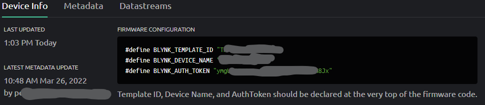
If you have an existing Legacy sketch then it’s fairly easy to convert in most cases, it just needs these two lines adding at the top:
The template ID and device name, along with the auth token come from the web console of Blynk IoT.
You’ll also need to create datastreams (previously the datastreams of V0 - V255 already existed, you now have to define them manually because they are now much more configurable).
Also, if you use notifications then these are handled differently.
BTW, Edgent uses Blynk.config and Blynk,begin in the background, which are the non-blocking version of Blynk.begin.
When you create a datastream the min/max values default to 0/1 (unless it’s s string). If you send data outside of these min/max values it will be ignored, without any warning that this has happened. So, set sensible (or excessive) min/max values.
If youre a fan of Blynk.syncAll then it will now only sync the datastreams that have the “Sync with latest server value every time device connects to the cloud” option enabled in the Advanced datastream setup.
The system allows you to create Digital Pin datastreams, but I don’t think this works as well as it did in Legacy. Personally, I’d stick to virtual pin datstreams.
The web dashboard has two views, Template and Device. You start by creating a template, then add devices based on that template… In Template view you can also add some basic widgets which allow you to do some of the things that you’d normally do in the app. Things that confuse people are:
If you add a widget to the web dashboard it won’t appear on the mobile app and vice-versa
Template view gives you a visual representation of what the web dashboard will look like, but this uses dummy data. If you’re looking at the dashboard in Template view and wondering why the values aren’t changing then you need to switch to device view (the spyglass icon at the top left)
Ok after understanding how the Edgent works, I realised for now that functionality is not going to be used by me. So went back to basics and created a simple App with a LED and Switch. Works fine. But of course this is on a college project level … no handling for failed WiFi links / Blynk server dropouts due to connectivity and so on. I know I need to bring in those. But would like comments on this code for a base level.
/****************************************************
  09 April 2022

  Basic template for ESP8266 based projects.

  Hardware used is WeMos8266withSSD1306 display
 ****************************************************/

#define BLYNK_TEMPLATE_ID "xxxxxxxxx"
#define BLYNK_DEVICE_NAME "yyyyyyy"
#include <ESP8266WiFi.h>
#include <BlynkSimpleEsp8266.h>

char auth[] = "wwwwwwwwwwwwwwwww";
char ssid[] = "eeeeeeeeeeeeeeee";
char pass[] = "xxxxxxxxxx";

BlynkTimer timer;

/* Comment this out to disable prints and save space */
#define BLYNK_PRINT Serial


//@@@@@@@@@@@@@@@@@@@@@@@@@@@@@@@@@@@@@@@@@@@@@@@@@

void setup()
{
  Serial.begin(9600);
  delay(1000);
  pinMode(LED_BUILTIN, OUTPUT);                      // Lights up for LOW ..
  digitalWrite(LED_BUILTIN, HIGH);

  // Attempt to connect to Blynk server
  Serial.println ("Trying connection to Blynk");
  Blynk.begin(auth, ssid, pass);

  // Check status of Blynk connection
  if (Blynk.connected()) {
    Serial.println ("Connected to Blynk");
    digitalWrite(LED_BUILTIN, LOW);
  }
  else
  {
    Serial.println("Blynk connection failed - Reset and try");
  }
}

  //**************************************************

  void loop()
  {
    Blynk.run();
  }

  //@@@@@@@@@@@@@@@@@@@@@@@@@@@@@@@@@@@@@@@@@@@@@@@@@@


  BLYNK_WRITE(V1)                                    // Handle Switch & LED
  {
    // Read Switch state
    int swtVal = param.asInt();

    // Update LED state
    Blynk.virtualWrite(V0, swtVal);
  }

  //***************************************************
where you use the rather clunky method of retaining the auth variable and making it equal to the BLYNK_AUTH_TOKEN variable that you’ve just copy/pasted, or change the Blynk.begin command to this:
Blynk.begin(BLYNK_AUTH_TOKEN, ssid, pass);
74880 is usually a better baud rate to use with a NodeMCU, you get to see the device boot messages that way, instead of gibberish. You probably don’t need the 1 second delay either.
Blynk.Begin is a blocking function, so if the WiFi connection or connection to the Blynk server doesn’t work you’ll never get to any of the other code, so you’ll never see the “Serial.println(“Blynk connection failed - Reset and try”);” message.
You’ve created a BlynkTimer object, but you arent using it. If you did want to use it then it wouldn’t work because you’re missing timer.run(); in the void loop.
This may or may not work, depending on how you’ve configured your V0 datastream. Previously LED Widgets had 256 brightness levels (0-255), so you needed to write a 255 to the widget to turn it on at maximum brightness.
Now, it depends on the min/max values of the datastream. If you set these to 0-255 for V0 then you’ll need to write a 255 to V0 to turn the LED on at full brightness. If the datastream is 0-1 then a 1 will turn it on and a 0 will turn it off.
Also, you could probably simplify it to:
BLYNK_WRITE(V1) // Handle Switch & LED
{
Blynk.virtualWrite(V0, param.asInt());
}
Studied all your comments carefully ( God is in details ) and modified the code .
The Blynk.timer declaration was a carryover from previous code, and so removed it.
The Serial of my module does need the 1 sec delay to initialize even with 74880. Maybe a module issue.
And the point on the char auth[] saves lot of trouble as I now can just copy-paste from console and get going.
Yes the LED works fine as the range is just 0-1. Thanks for the simplified version - will use it.
I tried the earlier method of Blynk.config() and Blynk.connect() to make it non blocking. But this does not work with the latest version. Searching for the equivalent of same .
The update code …
/****************************************************
09 April 2022
Basic template for ESP8266 based projects.
Hardware used is WeMos8266withSSD1306 display
10 April 2022
This code does a simple job of lighting up a LED on the App
when the Switch on the App is switched ON. The Switch is
configured in SWITCH mode and not in PUSH mode
****************************************************/
#define BLYNK_TEMPLATE_ID "xxx"
#define BLYNK_DEVICE_NAME "xxx"
#define BLYNK_AUTH_TOKEN "xxx"
#include <ESP8266WiFi.h>
#include <BlynkSimpleEsp8266.h>
char auth[] = BLYNK_AUTH_TOKEN ;
char ssid[] = "xxx";
char pass[] = "xxx";
/* Comment this out to disable prints and save space */
#define BLYNK_PRINT Serial
//@@@@@@@@@@@@@@@@@@@@@@@@@@@@@@@@@@@@@@@@@@@@@@@@@
void setup()
{
  Serial.begin(9600);
  delay(1000);
pinMode(LED_BUILTIN, OUTPUT); // Lights up for LOW ..
digitalWrite(LED_BUILTIN, HIGH);
// Attempt to connect to Blynk server
Serial.println ("Trying connection to Blynk");
Blynk.begin(BLYNK_AUTH_TOKEN, ssid, pass);
// Check status of Blynk connection
if (Blynk.connected()) {
Serial.println ("Connected to Blynk");
digitalWrite(LED_BUILTIN, LOW);
}
else
{
Serial.println("Blynk connection failed - Reset and try");
}
}
//**************************************************
  void loop()
  {
    Blynk.run();
  }
//@@@@@@@@@@@@@@@@@@@@@@@@@@@@@@@@@@@@@@@@@@@@@@@@@@
BLYNK_WRITE(V1)                                    // Handle Switch & LED
  {
    // Read Switch state
    int swtVal = param.asInt();

    // Update LED state
    Blynk.virtualWrite(V0, swtVal);
  }
//***************************************************
@PeteKnight
So finally … a code that CAN be used as a base for further development !! Appreciate the help provided !
/****************************************************
  09 April 2022

  Basic template for ESP8266 based projects.
  Hardware used is WeMos8266withSSD1306 display

  10 April 2022
  This code does a simple job of lighting up a LED on the App
  when the Switch on the App is switched ON. The Switch is
  configured in SWITCH mode and not in PUSH mode

  Version V2 : Uses the non blocking Blynk.Connect()
  Okay !!
 ****************************************************/

// Get the following three variables from Blynk Console
#define BLYNK_TEMPLATE_ID "TEMPLATE"
#define BLYNK_DEVICE_NAME "NAME"
#define BLYNK_AUTH_TOKEN "TOKEN"

#include <ESP8266WiFi.h>
#include <BlynkSimpleEsp8266.h>

char ssid[] = "ssid";
char pass[] = "pwd";

int wifi_connect_max_retries = 10;
int wifi_connect_count = 0;

/* Comment this out to disable prints and save space */
#define BLYNK_PRINT Serial

//@@@@@@@@@@@@@@@@@@@@@@@@@@@@@@@@@@@@@@@@@@@@@@@@@

void setup()
{
  Serial.begin(9600);
  delay(1000);

  pinMode(LED_BUILTIN, OUTPUT);                      // Lights up for LOW ..
  digitalWrite(LED_BUILTIN, HIGH);

  Serial.println( " Connecting to WiFi !");

  WiFi_Connect() ;

  Blynk.config(BLYNK_AUTH_TOKEN, BLYNK_DEFAULT_DOMAIN, BLYNK_DEFAULT_PORT);
  Blynk.connect();                                // Wifi link ON. Attempt to connect to Blynk

  if ( Blynk.connected()) {
    Serial.println ( " Connection to Blynk Server succesfull ");
    digitalWrite(LED_BUILTIN, LOW);
  }
  else
  {
    Serial.println ( " Failed to connect to Blynk Server. Reset ");
  }
}

//**************************************************

void loop()
{
  Blynk.run();
}

//@@@@@@@@@@@@@@@@@@@@@@@@@@@@@@@@@@@@@@@@@@@@@@@@@@


BLYNK_WRITE(V1)                                    // Handle Switch & LED
{
  // Read Switch state
  int swtVal = param.asInt();

  // Update LED state
  Blynk.virtualWrite(V0, swtVal);
}

//***************************************************

void WiFi_Connect()
{
  Serial.println(F("Connecting to Wi-Fi"));

  if (WiFi.status() != WL_CONNECTED)
  {
    WiFi.begin(ssid, pass); // connect to the network
  }
  while (WiFi.status() != WL_CONNECTED  && wifi_connect_count < wifi_connect_max_retries) // Loop until we've connected, or reached the maximum number of attemps allowed
  {
    delay(5000);
    wifi_connect_count++;
    Serial.print(F("Wi-Fi connection - attempt number "));
    Serial.println(wifi_connect_count);
  }

  if (WiFi.status() == WL_CONNECTED)
  {
    WiFi.mode(WIFI_STA);
    Serial.println(F("Wi-Fi CONNECTED"));
    Serial.println();
  }
  else
  {
    Serial.println(F("WiFi Link failed. Check and retry !!"));
    Serial.println();
    while ( 1 == 1);
  }
}

//***************************************************
The while ( 1 == 1); basically means wait forever. Wouldn’t it be better to call an ESP.restart() to have the device reboot and keep trying, or simply remove the retry limit?
If you have a power outage, your current code will try to connect to WiFi for 10 x 1 seconds then stop. Your WiFi router will probably take several minutes to come up, so you’ll always have to manually restart your ESP device in this scenario.
I use a limit to the number of WiFi connection attempts so that if a device that has a manual switch (such as a Sonoff smart socket) cant connect to WiFi/Blynk then it enters “standalone mode” which still allows manual control of the device.
I also check if WiFi is connected before calling Blynk.connect, as that reduces an unnecessary delay. You can also specify a time-out period in Blynk.connect(timeout) to help with this, although Blynk will also try to re-connect each time it encounters a Blynk.run() command, so if you did go for the “offline mode” .then you need to check this before calling Blynk.run().
It’s also not a bad idea to call your WiFi_Connect() routine with a BlynkTimer every so often, to handle re-connects.
I have never used the Blynk.Edgent example, now I want to connect it and I have one simple question: do I understand correctly that if I loaded this example once, then in all my future code edits, I will have to load the same example , only with the addition of my edits? After all, otherwise, for example, an over-the-air update will not work after the first flashing, if it is not Blynk.Edgent? Or am I misunderstanding the essence of this example?
You would open the appropriate Blynk Edgent example for your device, modify it as required then save this file and upload it to your device via USB then provision the device via the app.
If you want to make changes you re-open your saved file, make the changes then upload it either directly via USB or by exporting the compiled binary and uploading that via Blynk.Air.
The upload does not overwrite the data assigned during the provisioning process, as this is held in NVRAM.
Thanks Pete.
That is, every time I load a sketch with changes and additions of anything, I have to fill in all those code tabs that are included in Blynk.Edgent.
Sorry, you write “Blynk.Edgegent”, but the documentation says “Blynk.Edgent”, is there any difference or is it just a printing error?
When you save the example file all of the other files (the tabs that you see in the IDE) are saved as well. When you re-open the file the tabs will re-appear. If you look at the folder where the sketch is saved you’ll see the .ino file and all of the .h files too.