I have a issue with my project, blynk disconnect in long term like is running well between 1-4 days. After that i need to reset manual the arduino to get conneted to blynk.
NOTE: Arduino is controlling well the humidity without connected to blynk.
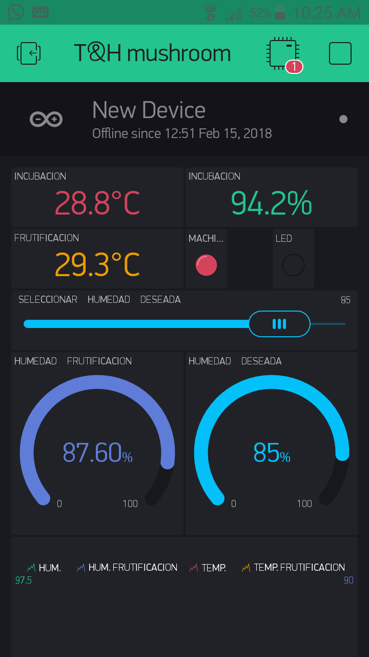
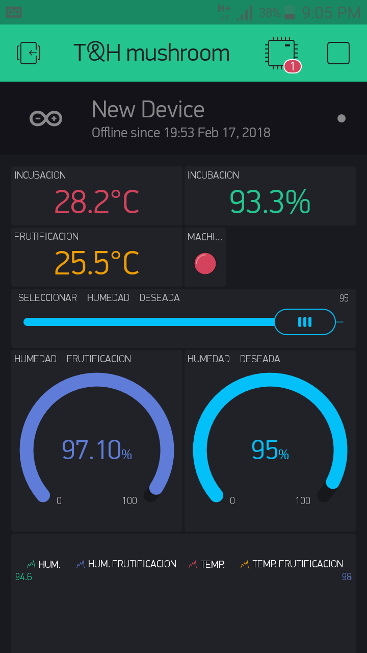
This project is a humidity controller for grow mushrooms.
Items List:
Arduino Uno
Relay module
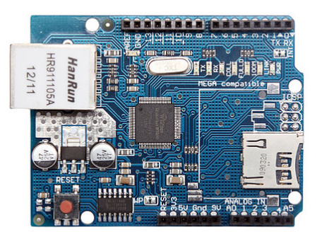
Ethernet Shield
Sensor Shield v5 (to have better wiring for sensors)
2 DHT22 Sensors
I use two sensors, one is just for reading and the other is for controlling humidity. The first sensor is wired 12m and the other 16m from the arduino. I use a electrovalve to control the water that goes in to mist system to reach humidity levels.
This code is based in @chrome1000 “ESP8266 HVAC control” project.
I’m thinking the ethernet.maintain(); is responsible for this, but I’m not sure. If I comment out that line it also compiles fine (and remove #include ethernet.h also). So I would suggest trying that and leave all the ethernet stuff to the Blynk library. It probably handles everything from there.
Also, I noticed that some ethernet boards can be really unstable. Which Ethernet board are you using?
Your sketch suggests you are using 4 pins on the Uno.
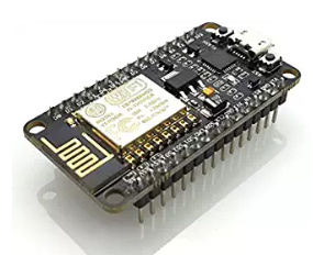
If this is the case I would order one of those super fast, high memory, plug and play ESP8266 development boards for $2.50.
Probably better than most of the Ethernet shields on the market, but that’s not really saying much.
After battling with these for a whild I eventually decided to take the plunge and go for a ESP8266 board to use instead of the Arduinio, which made the Ethernet shield redundant.
After a bit of wasted time/money I eventually settled ion the Wemos D1 Mini as my go-to board and haven’t touched an Arduino or those horrible Ethernet shields since.
Don’t be tempted to try using a Wi-Fi shield on the Auduino, or am ESP8266-01 as a Wi-Fi adapter for the Arduino, you’re wasting your time and money.
Yes i´m using 4 pins of the arduino, two pins for the sensor, one for the relay who control the misting system and other to control manually a ultrasonic humidifier.
Nooo!! Don’t use it as a Wi-Fi adaptor, use it instead of the Arduino. It has more memory and more processing power than the Arduino. With one of these (or preferably a Wemos D1 Mini) your Arduino and the Ethernet shield become an interesting paperweight.
11 digital input/output pins, all pins have interrupt/pwm/I2C/one-wire supported
Abstracted form “Wiki Wemos”>“D1 mini”>“Features”
Wemos DIgital pins can work like a “pwm Pin” from arduino? I´m asking this because i have wiring sensor cables in large distance, One have 16 meters and the other is 10 meters long.
With “pwm Pins” in arduino my sensors works great, I think that pins are 8 bytes signal.
the Arduino used 8 bit PWM and the Esp8266 uses 10 bit. What difference that would make in your scenario I have no idea.
The other thing to consider is that not all of the ESP8266 pins are actually usable in an everyday situation. A couple of them have ‘special’ uses and can cause issues when pulled high or low at boot-up, so are best avoided. I would have thought that in your case this won’t be a problem - though and as they only cost a few Pounds/Dollars/Euros each then you could give it a go anyway.
The other consideration is that as the Wemos devices are so small, and they use Wi-Fi, it might be possible for you to use multiple devices, one connected to each sensor, and have them physically located next to the sensor rather than using long wires to connect them. All you need it 5v of power for each device and if that would cause problems then you could maybe look at the threads on this forum about Deep Sleep and go for a battery powered option.
@PeteKnight yes the “WeMos” is a great board and you missed off the other very useful feature of auto updates from thousands of miles away. Must add more of their shares to my investment portfolio (only joking) but for many users it’s a near perfect board for working with Blynk and iOT projects.
It’s starting to sound like a Monty Python sketch…
“Alright - so apart from Wi-Fi, more memory, a faster processor, smaller size, lower power consumption, lower cost and the ability to do OTA updates; what has the WeMos ever done for us?”.