If you use the hardware serial Rx/Tx pins on an ESP8266 for communicating with a peripheral then you can’t use the same serial interface for debugging, which can be a pain.
The ESP has a second serial interface, which is Tx only, which can be used for debugging if necessary. You’ll need to define Serial1 and print your debug data to Serial1, and connect pin D8 to the Rx pin of a FTDI serial to USB interface.
All correct! The point is, I ALWAYS do EVERYTHING to use hardware serial lines, and I’m quite suspicious when someone states, that they are the source of problems.
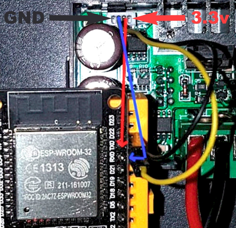
I have simplified the code, and now TX and RX are used in the ESP8266. The updates have to be by OTA, and I have removed the DHT to use a BMP180 that is smaller and works by i2c (D1 and D2).
The voltage 3.3v. I take it from the same cable as the rx-tx communication to supply the ESP8266
/*
        // DPS5005 with Blynk By Hussein Daj(www.hussein-solutions.de)
        // Credit to Luke 8)
        // Free to use this code how you like but please link my site

        // Credit to Doc Walker of ModbusMaster for making a great Arduino Library https://github.com/4-20ma/ModbusMaster
        */

        #include <ArduinoOTA.h>
        #include <ModbusMaster.h>   // ModbusMaster
        #include <ESP8266WiFi.h>
        #include <BlynkSimpleEsp8266.h>
        #include <Adafruit_BMP085.h>

        Adafruit_BMP085 bme;    // I2C D1 D2
        String myHostname = "DPS5005";  // Name for Host in the Network

        ModbusMaster node;    // instantiate ModbusMaster object
        float voltage = 0.0;
        float current = 0.0;
        float power = 0.0;
        float SetV = 0;
        float SetA = 0;
        bool on=0;
        char auth[] = "blynk code"; //الكود الخاص بمشروع بلنك
        char ssid[] = "your ssid";//اسم شبكة الواير ليس
        char pass[] = "ssid password";//كلمة السر
        BlynkTimer timer;

        void myTimerEvent()
        {
           Read();
          float T = bme.readTemperature();
          float p = bme.readPressure();
          Blynk.virtualWrite(V0,voltage); //out V
          Blynk.virtualWrite(V1,current); //out A
          Blynk.virtualWrite(V9,SetV); //SetV
          Blynk.virtualWrite(V8,SetA); //SetA
          Blynk.virtualWrite(V5,on); //on off state
          Blynk.virtualWrite(V2,power); //on off state
          Blynk.virtualWrite(V3, T);
          Blynk.virtualWrite(V4, p/100);
         }

        void setup()
        {
          Serial.begin(9600);
          WiFi.mode(WIFI_STA);
          WiFi.hostname(myHostname);
          timer.setInterval(1000L, myTimerEvent);
          Blynk.begin(auth, ssid, pass);
          bme.begin();
          node.begin(1,Serial);
          while (Blynk.connect() == false) {}
          ArduinoOTA.setHostname("DPS5005"); // OPTIONAL NAME
          ArduinoOTA.begin();
        }

        void loop()
        {
          Blynk.run();
          ArduinoOTA.handle();
          timer.run(); // Initiates BlynkTimer
        }

        //Read Data
        void Read(){
           uint8_t j, result;
            result = node.readHoldingRegisters(0, 10);  // slave: read a range of 16-bit registers starting at register 0 to 10
         if (result == node.ku8MBSuccess)   // only do something with data if read is successful
          {
           voltage =  ((float)node.getResponseBuffer(2) / 100 ); // get voltage from response buffer and convert to float
           current =  ((float)node.getResponseBuffer(3) / 1000 ); // get current from response buffer and convert to float
           power =  ((float)node.getResponseBuffer(4) / 100 ); // get power from response buffer and convert to float
           SetV =  ((float)node.getResponseBuffer(0) / 100 ); // get SetV from response buffer and convert to float
           SetA =  ((float)node.getResponseBuffer(1) / 1000 ); // get SetA from response buffer and convert to float
           on =  ((bool)node.getResponseBuffer(9) ); // Status on or off
        }
           }

        //Write Data
        BLYNK_WRITE(V5) //on off
        {
          int pinValue = param.asInt(); // assigning incoming value from pin V5 to a variable
           node.writeSingleRegister(9, pinValue); //set power on !

        }

        BLYNK_WRITE(V6) //Set V
        {
          int pinValue = param.asFloat(); // assigning incoming value from pin V5 to a variable
          node.writeSingleRegister(0, pinValue*10);
        }

        BLYNK_WRITE(V7) //Set A
        {
          int pinValue = param.asFloat(); // assigning incoming value from pin V5 to a variable
        node.writeSingleRegister(1, pinValue*100);
        }
Hello!
I tried your example on my esp8266 and it keeps restarting every few seconds.Do you have any advices? I also added yield(); hoping it will solve the problem, but it does not.
Thank you!
How strange, I’ve been working for a long time and it has never been restart.
Do you have updated blynk?
The power is to the 3.3v pin, I do not use the microusb connector.
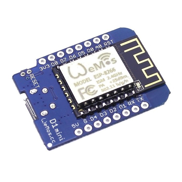
Edit, it could be for the model, I use the wemos d1 mini
Hi, yesterday my esp8266 failed me. After checking everything, I discovered that it failed in the “Adafruit_BMP085.h” library.
I replaced the library with “SFE_BMP180.h” and now it works correctly.
I have marked the lines of the BMP180, in case the error returned, for eliminate them easily.
I have also added V4 for see input voltage, just like on the screen.
I’m sorry I took so long to give a solution.
/*
        // DPS5005 with Blynk By Hussein Daj(www.hussein-solutions.de)
        // Credit to Luke 8)
        // Free to use this code how you like but please link my site
    // Credit to Doc Walker of ModbusMaster for making a great Arduino Library https://github.com/4-20ma/ModbusMaster
            */

    #include <ArduinoOTA.h>
    #include <ModbusMaster.h>   // ModbusMaster
    #include <ESP8266WiFi.h>
    #include <BlynkSimpleEsp8266.h>
    #include <SFE_BMP180.h> //BMP180

    SFE_BMP180 temp;    // BMP180 I2C D1 D2
    String myHostname = "DPS5005";  // Name for Host in the Network

    ModbusMaster node;    // instantiate ModbusMaster object
    float voltage = 0.0;
    float current = 0.0;
    float power = 0.0;
    float vin = 0.0;
    float SetV = 0;
    float SetA = 0;
    bool on=0;
    char auth[] = "blynk code"; //الكود الخاص بمشروع بلنك
    char ssid[] = "your ssid";//اسم شبكة الواير ليس
    char pass[] = "ssid password";//كلمة السر
    char status; //BMP180
    double T;    //BMP180
    BlynkTimer timer;

    void myTimerEvent()
    {
       Read();
      Blynk.virtualWrite(V0,voltage); //out V
      Blynk.virtualWrite(V1,current); //out A
      Blynk.virtualWrite(V4,vin); //in V --> New
      Blynk.virtualWrite(V9,SetV); //SetV
      Blynk.virtualWrite(V8,SetA); //SetA
      Blynk.virtualWrite(V5,on); //on off state
      Blynk.virtualWrite(V2,power); //on off state
      Blynk.virtualWrite(V3, T);
     }

    void setup()
    {
      Serial.begin(9600);
      WiFi.mode(WIFI_STA);
      WiFi.hostname(myHostname);
      timer.setInterval(1000L, myTimerEvent);
      Blynk.begin(auth, ssid, pass);
      temp.begin(); //BMP180
      node.begin(1,Serial);
      while (Blynk.connect() == false) {}
      ArduinoOTA.setHostname("DPS5005"); // OPTIONAL NAME
      ArduinoOTA.begin();
    }


    void loop()
    {
      Blynk.run();
      ArduinoOTA.handle();
      status = temp.startTemperature(); //BMP180
      status = temp.getTemperature(T); //BMP180
      timer.run(); // Initiates BlynkTimer
    }

    //Read Data
    void Read(){
       uint8_t j, result;
        result = node.readHoldingRegisters(0, 10);  // slave: read a range of 16-bit registers starting at register 0 to 10
     if (result == node.ku8MBSuccess)   // only do something with data if read is successful
      {
       voltage =  ((float)node.getResponseBuffer(2) / 100 ); // get voltage from response buffer and convert to float
       current =  ((float)node.getResponseBuffer(3) / 1000 ); // get current from response buffer and convert to float
       power =  ((float)node.getResponseBuffer(4) / 100 ); // get power from response buffer and convert to float
       vin =  ((float)node.getResponseBuffer(5) / 100 ); // get in voltage from response buffer and convert to float ---> Input Voltage
       SetV =  ((float)node.getResponseBuffer(0) / 100 ); // get SetV from response buffer and convert to float
       SetA =  ((float)node.getResponseBuffer(1) / 1000 ); // get SetA from response buffer and convert to float
       on =  ((bool)node.getResponseBuffer(9) ); // Status on or off
    }
       }

    //Write Data
    BLYNK_WRITE(V5) //on off
    {
      int pinValue = param.asInt(); // assigning incoming value from pin V5 to a variable
       node.writeSingleRegister(9, pinValue); //set power on !

    }

    BLYNK_WRITE(V6) //Set V
    {
      int pinValue = param.asFloat(); // assigning incoming value from pin V5 to a variable
      node.writeSingleRegister(0, pinValue*10);
    }

    BLYNK_WRITE(V7) //Set A
    {
      int pinValue = param.asFloat(); // assigning incoming value from pin V5 to a variable
    node.writeSingleRegister(1, pinValue*100);
    }</code></pre>
Very nice with project .
1)I would like to Know How u selecting Device ID for the project.
2) Function code for project
3)What Result will be represent Here. Where all the values being stored.
 The point is, I ALWAYS do EVERYTHING to use hardware serial lines, and I’m quite suspicious when someone states, that they are the source of problems.