Blynk connected, MCU Node recognised but LED wont work

Good day,
I am new to Blynk.
Recently I started a LED test to see if my MCU Node was working. I have been through everything and in theory it should be working but the LED wont switch on. I tried another MCU Node and it has the same result.

This is my checklist:
1). I am connected to my WIFI- check
2). Code uploaded- check
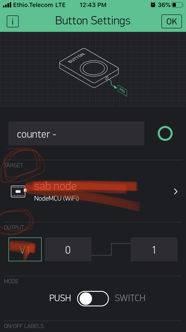
3). Blynk App project is connected
4). Checked LED connections good
5). Running MCU Node off my computer with USB.

So in a nutshell, everything is connected, check my pins to see if positioned correctly- all good
I have been busy with it for a few days now and am using this forum as a last resort.

This is the code I am using

#define BLYNK_PRINT Serial
#include <WiFi.h>
#include <WiFiClient.h>
#include <BlynkSimpleEsp32.h>
int pin = 2;
char auth[] = "slxR94******************Ki3h87k_lEti";       // You should get Auth Token in the Blynk App.
char ssid[] = " ********** ";                    // Your Wi-Fi Credentials
char pass[] = " ********** ";
void setup() {  
  pinMode(pin, OUTPUT); 
  pinMode(pin, HIGH);
  Serial.begin(9600);
  delay(10);
  Serial.print("Connecting to ");
  Serial.println(ssid);
  WiFi.begin(ssid, pass);
  int wifi_ctr = 0;
  while (WiFi.status() != WL_CONNECTED) {
  delay(500);
  Serial.print(".");
  }
  Serial.println("WiFi connected");  
  Blynk.begin("slxR94BL*****************h87k_lEti", ssid, pass);
}
void loop(){
    Blynk.run();
}

Any help would be greatly appreciated.
Regards,
Martin

pinMode(pin, OUTPUT);
DigitalWrite(pin, HIGH);

Thanks Proietti,

I tried that but still nothing.

@Martin.A please edit your post and add triple backticks at the beginning and end of your code so that it displays correctly.
Triple backticks look like this:
```

Pete.

1 Like

Thanks Pete, I edited the sketch, I thought I read that the asterisk was also okay. My mistake.

Does this line still exist in your current code?

What device type did you choose in the app?

This implies that you have connected an Led to GPIO2 (the pin labelled D4), in addition to the onboard LED which is connected to the same pin. What is the other side of your LED connected to, and what size of inline resistor have you used?

Pete.

Maybe app side. Do you have the correct device selected in the app, and also the D4 pin on the button? No idea how green you are, you may be a pro… but even pros miss the obvious some times…

Judging from his code above he has no interaction with the app. All that code does or should do is turn on a led attached at GPIO2 at start up

@Martin.A can you confirm the pin? Is it GPIO2 which is D4 or is D2

I assume there is an app button attached to digital pin, which is why I asked the question about the app, but it’s radio silence at the moment.

Pete.