Hi I have a problem.
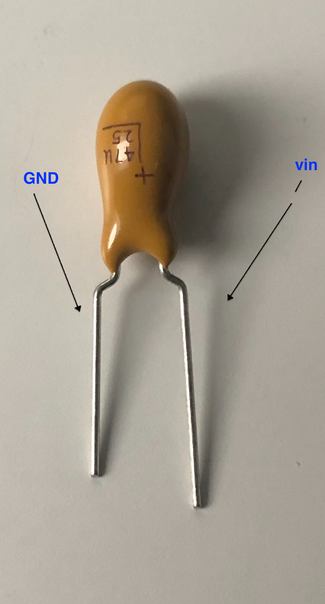
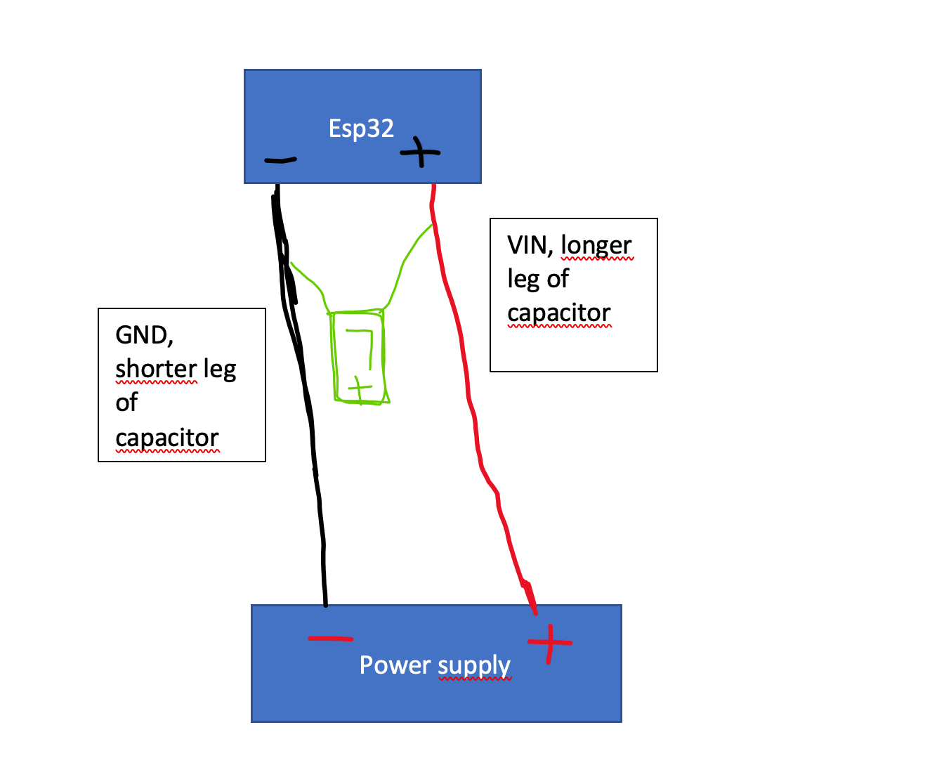
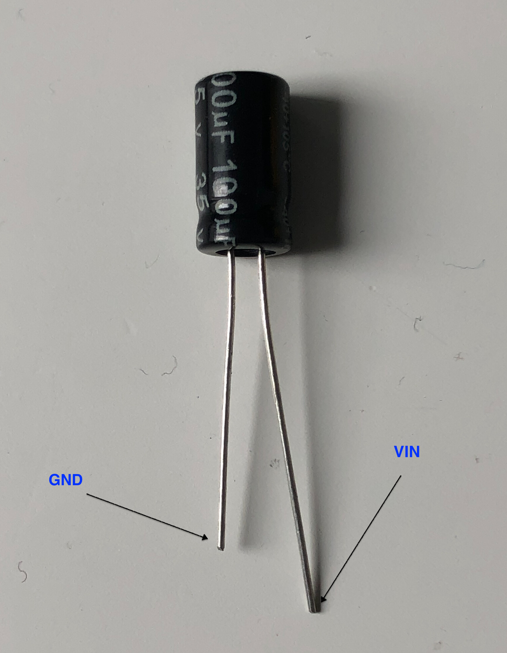
My blynk app disconnects with esp32 or refuses to connect. I supply power to esp32 and other things and when esp32 works on this supply it does not connect. But if I disconnect vin from esp32 and supply power only to it via micro usb cable, it works. Then I connect it to the normal power supply and it’s still connected to micro usb and it works. When I remove micro usb it works for 10 mins and then stops working (disconnects) (led on it still shines).
Here’s code:
float MaxTemp = 0;
int MaxMoist = 0;
int MinMoist = 0;
int x = 0;
float temperatureIN = 0;
#include <Adafruit_Sensor.h>
#include "Adafruit_TSL2591.h"
Adafruit_TSL2591 tsl = Adafruit_TSL2591(2591);
#define pump 26
int ElFan = 12;
int PlFan = 32;
int soilMoisture = 0;
int soilMoistureSensor = 34;
int gBright = 0;
int rBright = 213;
int bBright = 42;
#include <analogWrite.h>
#define RED_LED 14
#define BLUE_LED 19
#define GREEN_LED 27
#define BLYNK_PRINT Serial
#include <WiFi.h>
#include <WiFiClient.h>
#include <BlynkSimpleEsp32.h>

char ssid[] = "****";
char pass[] = "-----;
char auth[] = "pass";
BlynkTimer timer;
boolean stateled=0;
boolean prevStateled=0;
 #define BLYNK_MSG_LIMIT 20
#include <OneWire.h>
#include <DallasTemperature.h>
float tempC = 0;

// Data wire is plugged into port 2 on the Arduino
#define ONE_WIRE_BUS 15

// Setup a oneWire instance to communicate with any OneWire devices
OneWire oneWire(ONE_WIRE_BUS);

// Pass our oneWire reference to Dallas Temperature.
DallasTemperature sensors(&oneWire);

// Addresses of 3 DS18B20s
uint8_t sensor1[8] = { 0x28, 0xFF, 0xCD, 0xAC, 0x02, 0x19, 0x8A, 0xDE };
uint8_t sensor2[8] = { 0x28, 0xFF, 0xED, 0xAD, 0x02, 0x19, 0x8A, 0xA9 };
void printTemperature(DeviceAddress deviceAdress){

}
BLYNK_READ(V2) {

 Blynk.virtualWrite(2,analogRead(soilMoistureSensor)/37);

}
BLYNK_READ(V1) {

 Blynk.virtualWrite(1,tsl.getLuminosity(TSL2591_VISIBLE));

}
BLYNK_READ(V3) {
  float tempC = sensors.getTempC(sensor1 );
  Blynk.virtualWrite(3, tempC);
}
BLYNK_WRITE(V4)
{
  MinMoist = param.asInt();
  if ( analogRead(soilMoistureSensor)/37< MinMoist){
    digitalWrite(pump,HIGH);
  }

}
BLYNK_WRITE(V7) {
  MaxMoist = param.asInt();
  if(analogRead(soilMoistureSensor)/37 > MaxMoist) {
    digitalWrite(pump,LOW);
  }
}
BLYNK_WRITE(V8) {
  MaxTemp = param.asInt();
  if(sensors.getTempC(sensor1 ) > MaxTemp){
    digitalWrite(PlFan,HIGH);

  }
  else {
    digitalWrite(PlFan, LOW);
  }
}
void simpleRead(void)
{
  // Simple data read example. Just read the infrared, fullspecrtrum diode
  // or 'visible' (difference between the two) channels.
  // This can take 100-600 milliseconds! Uncomment whichever of the following you want to read
  uint16_t x = tsl.getLuminosity(TSL2591_VISIBLE);
  //uint16_t x = tsl.getLuminosity(TSL2591_FULLSPECTRUM);
  //uint16_t x = tsl.getLuminosity(TSL2591_INFRARED);

  Serial.print(F("[ ")); Serial.print(millis()); Serial.print(F(" ms ] "));
  Serial.print(F("Luminosity: "));
  Serial.println(x, DEC);
}
void setup(void)
{
  pinMode(PlFan, OUTPUT);
  configureSensor();
  pinMode(ElFan, OUTPUT);
  sensors.begin();
  pinMode(soilMoistureSensor, INPUT_PULLUP);
  pinMode(pump, OUTPUT);
  // Debug console
  Serial.begin(115200);
  pinMode(13,OUTPUT); // NODEMCU PIN D7
  Blynk.begin(auth, ssid, pass, "blynk-cloud.com", 8442);
  timer.setInterval(300L, checkledstate);
 //  attachInterrupt(digitalPinToInterrupt(13), notifyOnled, CHANGE);
}

BLYNK_WRITE(V6)
{
    if (param.asInt()){
   analogWrite(GREEN_LED, gBright);
  analogWrite(RED_LED, rBright);
  analogWrite(BLUE_LED, bBright);
   Blynk.virtualWrite(V13,1);
    } else {
      analogWrite(GREEN_LED,0);
  analogWrite(RED_LED, 0);
  analogWrite(BLUE_LED, 0);
  Blynk.virtualWrite(V13,0);
    }
}


void loop(){
simpleRead();
 ElWent();
   sensors.requestTemperatures();
  if (Blynk.connected())
  {
    Blynk.run();
  }
   timer.run();
}

BLYNK_CONNECTED()
{
  Blynk.syncVirtual(V6);

}
void checkledstate()
{

  stateled=digitalRead(13);
  if (stateled!=prevStateled)
  {
    if (stateled==0) Blynk.virtualWrite(V13,0);
    if (stateled==1) Blynk.virtualWrite(V13,255);
  }
  prevStateled=stateled;
}
void ElWent (){
  if(temperatureIN >= 35) {
    digitalWrite(ElFan, HIGH);
  }
  else{
    digitalWrite(ElFan, LOW);
  }
}void configureSensor(void)
{
  // You can change the gain on the fly, to adapt to brighter/dimmer light situations
  //tsl.setGain(TSL2591_GAIN_LOW);    // 1x gain (bright light)
  tsl.setGain(TSL2591_GAIN_MED);      // 25x gain
  //tsl.setGain(TSL2591_GAIN_HIGH);   // 428x gain

  // Changing the integration time gives you a longer time over which to sense light
  // longer timelines are slower, but are good in very low light situtations!
  //tsl.setTiming(TSL2591_INTEGRATIONTIME_100MS);  // shortest integration time (bright light)
  // tsl.setTiming(TSL2591_INTEGRATIONTIME_200MS);
  tsl.setTiming(TSL2591_INTEGRATIONTIME_300MS);
  // tsl.setTiming(TSL2591_INTEGRATIONTIME_400MS);
  // tsl.setTiming(TSL2591_INTEGRATIONTIME_500MS);
  // tsl.setTiming(TSL2591_INTEGRATIONTIME_600MS);  // longest integration time (dim light)

  /* Display the gain and integration time for reference sake */
  Serial.println(F("------------------------------------"));
  Serial.print  (F("Gain:         "));
  tsl2591Gain_t gain = tsl.getGain();
  switch(gain)
  {
    case TSL2591_GAIN_LOW:
      Serial.println(F("1x (Low)"));
      break;
    case TSL2591_GAIN_MED:
      Serial.println(F("25x (Medium)"));
      break;
    case TSL2591_GAIN_HIGH:
      Serial.println(F("428x (High)"));
      break;
    case TSL2591_GAIN_MAX:
      Serial.println(F("9876x (Max)"));
      break;
  }
  Serial.print  (F("Timing:       "));
  Serial.print((tsl.getTiming() + 1) * 100, DEC);
  Serial.println(F(" ms"));
  Serial.println(F("------------------------------------"));
  Serial.println(F(""));
}
please help
Maciek
 .
.