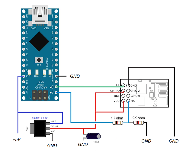
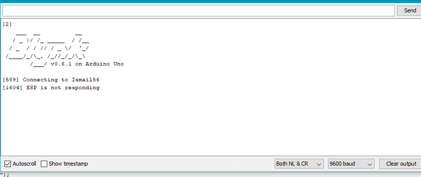
Hi, can anyone please help with this? I’m using Arduino Uno ans Esp 8266-01s for this project. My LCD (16x2) turn ON but cannot display alphabet through hardware and my wifi module doesn’t seem to connect. The connection banknotes and coins as inputs for the donation box. The coins will then be calculated directly using an
IR reflective sensor. For ESP8266 i using LC04A to ESP8266 accepts 5V signal into RX and the 3.3v it puts out of TX. From LC04A HR1 connect to pin 10 arduino and HT1 to pin 9 arduino for TX and RX. From LC04A LT1 connect to TX (esp8266) and LR1 to RX (esp8266).
Here my codes:
#define BLYNK_PRINT Serial
#include <ESP8266_Lib.h>
#include <BlynkSimpleShieldEsp8266.h>
char auth[] = "neWsZJyui_dp_0f80lfH_5m8vIP0y_-r";
#define EspSerial Serial1
#include <SoftwareSerial.h>
SoftwareSerial EspSerial(9, 10); // RX, TX
#define ESP8266_BAUD 9600
ESP8266 wifi(&EspSerial);
char ssid[] = "Ismail56";
char pass[] = "610101715450A";
#include <Wire.h>
#include <LiquidCrystal_I2C.h>
#include <EEPROM.h>
#define S0 4
#define S1 5
#define S2 6
#define S3 7
#define outPin 8
LiquidCrystal_I2C lcd(0x27,16,2); // 0x27 is the I2C bus address for an unmodified module
//Coin Money define
const int coi10n = 11; //input from ir sensor
const int coi20n = 12;
const int coi50n = 13;
const int rm = 2;
const int motor = 3;
int ir10,ir20,ir50 = 0;
int cnt10r,cnt20r,cnt50r = 0;
float cnttotal = 0;
//Paper Money define
int rm1,rm5,rm10,rm20,rm50,rm100 = 0;
int rmt100r,rmt500r,rmt1000r,rmt2000r,rmt5000r,rmt10000r =0;
float rmttotal = 0;
// Stores frequency read by the photodiodes
boolean DEBUG = true;
int redFrequency = 0;
int greenFrequency = 0;
int blueFrequency = 0;
// Stores the red. green and blue colors
int red = 0;
int grn = 0;
int blu = 0;
String color ="";
int count = 0;
long startTiming = 0;
long elapsedTime =0;
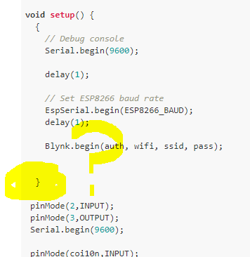
void setup() {
{
// Debug console
Serial.begin(9600);
delay(1);
// Set ESP8266 baud rate
EspSerial.begin(ESP8266_BAUD);
delay(1);
Blynk.begin(auth, wifi, ssid, pass);
}
pinMode(2,INPUT);
pinMode(3,OUTPUT);
Serial.begin(9600);
pinMode(coi10n,INPUT);
pinMode(coi20n,INPUT);
pinMode(coi50n,INPUT);
lcd.begin(16,2);
lcd.backlight(); // You can turn the backlight off by setting it to LOW instead of HIGH
lcd.write(EEPROM.read(5));
// Setting the outputs
pinMode(S0, OUTPUT);
pinMode(S1, OUTPUT);
pinMode(S2, OUTPUT);
pinMode(S3, OUTPUT);
// Setting the sensorOut as an input
pinMode(outPin, INPUT);
// Setting frequency scaling to 20%
digitalWrite(S0,HIGH);
digitalWrite(S1,LOW);
// Begins serial communication
Serial.begin(9600);
Serial.println("Paper Money Color Detector");
startTiming = millis();
}
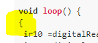
void loop() {
{
ir10 =digitalRead(coi10n); //read the state of coi100n and store it as ir100
ir20 =digitalRead(coi20n); //read the state of coi100n and store it as ir200
ir50=digitalRead(coi50n); //read the state of coi100n and store it as ir500
if(ir10 ==LOW){cnt10r+=10; delay(300);}
Blynk.virtualWrite(V1,cnt10r);
if(ir20 ==LOW){cnt20r+=20; delay(300);}
Blynk.virtualWrite(V2,cnt20r);
if(ir50 ==LOW){cnt50r+=50; delay(300);}
Blynk.virtualWrite(V3,cnt50r);
cnttotal =cnt10r+cnt20r+cnt50r;
cnttotal = cnttotal/100;
Blynk.virtualWrite(V4,cnttotal);
EEPROM.write(5,cnttotal);
Serial.println(EEPROM.read(5));
lcd.setCursor(0,0);
lcd.print("TOTAL COIN :");
lcd.setCursor(1,1);
lcd.print(cnttotal);
}
{
if(digitalRead(2)==1)
{
Serial.println(digitalRead(2));
digitalWrite(3,HIGH);
delay(100);
}
else
{
digitalWrite(3,LOW);
}
}
{
//read red component
digitalWrite(S2, LOW);
digitalWrite(S3, LOW);
redFrequency = pulseIn(outPin, LOW);
Serial.print(" Red = ");
Serial.print(redFrequency);
Blynk.virtualWrite(V5,redFrequency);
delay(400);
//read green component
digitalWrite(S2, HIGH);
digitalWrite(S3, HIGH);
greenFrequency = pulseIn(outPin, LOW);
Serial.print(" Green = ");
Serial.print(greenFrequency);
Blynk.virtualWrite(V6,greenFrequency);
delay(400);
//let's read blue component
digitalWrite(S2, LOW);
digitalWrite(S3, HIGH);
blueFrequency = pulseIn(outPin, LOW);
Serial.print(" Blue = ");
Serial.println(blueFrequency);
Blynk.virtualWrite(V7,blueFrequency);
delay(400);
// Checks the current detected color and prints
// a message in the serial monitor
// for RM10 color frequency - OK
if ((redFrequency >= 85 && redFrequency <= 105) &&
(greenFrequency >= 115 && greenFrequency <= 125) &&
(blueFrequency >= 100 && blueFrequency <= 115))
{
Serial.println(" - RM10 detected!");
{rmt1000r+=1000; delay(600);}
}
// for RM20 color frequency
if ((redFrequency >= 90 && redFrequency <= 105) &&
(greenFrequency >= 105 && greenFrequency <= 124) &&
(blueFrequency >= 100 && blueFrequency <= 116))
{
Serial.println(" - RM20 detected!");
{rmt2000r+=2000; delay(600);}
}
// for RM5 color frequency - OK
else if ((redFrequency >= 100 && redFrequency <= 120) &&
(greenFrequency >= 95 && greenFrequency <= 110) &&
(blueFrequency >= 90 && blueFrequency <= 110))
{
Serial.println(" - RM5 detected!");
{rmt500r+=500; delay(600);}
}
// for RM1 color frequency - OK
else if ((redFrequency >= 120 && redFrequency <= 138) &&
(greenFrequency >= 128 && greenFrequency <= 136) &&
(blueFrequency >= 85 && blueFrequency <= 105))
{
Serial.println(" - RM1 detected!");
{rmt100r+=100; delay(600);}
}
// for RM50 color frequency
else if ((redFrequency >= 26 && redFrequency <= 52) &&
(greenFrequency >= 44 && greenFrequency <= 63) &&
(blueFrequency >= 39 && blueFrequency <= 65))
{
Serial.println(" - RM50 detected!");
{rmt5000r+=5000; delay(600);}
}
// for RM100 color frequency
else if ((redFrequency >= 26 && redFrequency <= 52) &&
(greenFrequency >= 44 && greenFrequency <= 63) &&
(blueFrequency >= 39 && blueFrequency <= 65))
{
Serial.println(" - RM100 detected!");
{rmt10000r+=10000; delay(600);}
}
rmttotal = rmt100r+rmt500r+rmt1000r,rmt2000r,rmt5000r,rmt10000r;
rmttotal = rmttotal/100;
Blynk.virtualWrite(V8,rmttotal);
EEPROM.write(5,rmttotal);
Serial.println(EEPROM.read(5));
Serial.println("TOTAL PAPER MONEY :");
Serial.println(rmttotal);
}
{
Blynk.run();
}
}