I need help. My home project is that I read the temperature from the ds18b20 sensor connected to the esp8266 nodemcu v3. I display the temperature on the 20x4 LCD and on the phone using Blynk. When I am using the BlynkEdgent.h library
When I use the BlynkSimpleEsp8266.h library instead of BlynkEdgent.h, I provide the token and wifi data, it all displays fine. And I’d like to use Blynk 2.0 and BlynkEgent.
#define BLYNK_TEMPLATE_ID "TMPLpmwDx25f"
#define BLYNK_DEVICE_NAME "TERMOMETR WIFI"
#define BLYNK_FIRMWARE_VERSION        "0.1.0"
#define BLYNK_PRINT Serial
#define BLYNK_DEBUG
#define APP_DEBUG
#include "BlynkEdgent.h"
#include <DallasTemperature.h>
#include <OneWire.h>
#include <Wire.h>
#include <TimeLib.h>
#include <WidgetRTC.h>
#include <SPI.h>
#include <LiquidCrystal_PCF8574.h>
LiquidCrystal_PCF8574 lcd(0x27);
WidgetRTC rtc;

#define ONE_WIRE_BUS 0 // D3
#define TEMPERATURE_PRECISION 12
OneWire oneWire(ONE_WIRE_BUS);
DallasTemperature sensors(&oneWire);
BlynkTimer timer;

float temp1=0;
WidgetLED led7(V13);


BLYNK_CONNECTED()
{
Blynk.syncAll();
}

void temp()
{
temp1 = sensors.getTempCByIndex(0);
sensors.requestTemperatures();

Blynk.virtualWrite(0,temp1); //GLOWICA
Blynk.syncVirtual(V13);
}

void ledonline()
{
  if (led7.getValue()) {
    led7.off();
  } else {
    led7.on();
  }
}


void loop() {
sensors.requestTemperatures();

lcd.setCursor(0, 0);
lcd.print("1" );
lcd.setCursor (13, 0);
lcd.print(temp1);
lcd.print((char)223);
lcd.print("C");


Blynk.run();
timer.run();
BlynkEdgent.run();
}

void setup()
{
Serial.begin(115200);
lcd.begin(20,4);
lcd.setBacklight(255);
lcd.setCursor(0, 0);
lcd.print("hELLO" );
lcd.setCursor(0, 1);
lcd.print("wORLD" );


delay(6000);
lcd.clear();

timer.setInterval(1000L, ledonline);
timer.setInterval(1000L, temp);
BlynkEdgent.begin();
}
first clean your void loop and stage your setinterval
and try this
BlynkEdgent.begin(); // <--- must be before setinterval
timer.setInterval(1000L, ledonline);
timer.setInterval(1050L, temp);
Take a look in the Settings.h tab.
Pete.
Hi Pete.
You’re displaying this info before calling Edgent.begin()
Pete.
1 Like
The corrections proposed by you do not help https://www.youtube.com/watch?v=ux-WaEdW0WA
the device is online, but the LCD and the temperature reading from the sensor are not working
#define BLYNK_TEMPLATE_ID "TMPLpmwDx25f"
#define BLYNK_DEVICE_NAME "TERMOMETR WIFI"
#define BLYNK_FIRMWARE_VERSION        "0.1.0"
#define BLYNK_PRINT Serial
#define BLYNK_DEBUG
#define APP_DEBUG
#include "BlynkEdgent.h"
#include <DallasTemperature.h>
#include <OneWire.h>
#include <Wire.h>
#include <TimeLib.h>
#include <WidgetRTC.h>
#include <SPI.h>
#include <LiquidCrystal_PCF8574.h>
LiquidCrystal_PCF8574 lcd(0x27);
WidgetRTC rtc;

#define ONE_WIRE_BUS 0 // D3
#define TEMPERATURE_PRECISION 12
OneWire oneWire(ONE_WIRE_BUS);
DallasTemperature sensors(&oneWire);
BlynkTimer timer;

float temp1=0;
WidgetLED led7(V13);


BLYNK_CONNECTED()
{
Blynk.syncAll();
}

void temp()
{
temp1 = sensors.getTempCByIndex(0);
sensors.requestTemperatures();

Blynk.virtualWrite(0,temp1); //GLOWICA
Blynk.syncVirtual(V13);
}

void ledonline()
{
  if (led7.getValue()) {
    led7.off();
  } else {
    led7.on();
  }
}


void loop() {
BlynkEdgent.run();
lcd.print("hELLO" );


}

void setup()
{
Serial.begin(115200);
lcd.begin(20,4);
lcd.setBacklight(255);
lcd.setCursor(0, 0);
lcd.print("hELLO" );
lcd.setCursor(0, 1);
lcd.print("wORLD" );


delay(6000);
lcd.clear();

BlynkEdgent.begin(); // <--- must be before setinterval
timer.setInterval(1000L, ledonline);
timer.setInterval(1050L, temp);

}
Without knowing how your hardware is connected, and what you have in your Settings.h it’s very difficult to help further.
Pete.
I have this connection like this:
settings.h
/*
 * Board configuration (see examples below).
 */

#if defined(USE_NODE_MCU_BOARD) || defined(USE_WEMOS_D1_MINI)

  #define BOARD_BUTTON_PIN            0
  #define BOARD_BUTTON_ACTIVE_LOW     true

  #define BOARD_LED_PIN               2
  #define BOARD_LED_INVERSE           true
  #define BOARD_LED_BRIGHTNESS        255

#elif defined(USE_SPARKFUN_BLYNK_BOARD)

  #define BOARD_BUTTON_PIN            0
  #define BOARD_BUTTON_ACTIVE_LOW     true

  #define BOARD_LED_PIN_WS2812        4
  #define BOARD_LED_BRIGHTNESS        64

#elif defined(USE_WITTY_CLOUD_BOARD)

  #define BOARD_BUTTON_PIN            4
  #define BOARD_BUTTON_ACTIVE_LOW     true

  #define BOARD_LED_PIN_R             15
  #define BOARD_LED_PIN_G             12
  #define BOARD_LED_PIN_B             13
  #define BOARD_LED_INVERSE           false
  #define BOARD_LED_BRIGHTNESS        64

#else

  #warning "Custom board configuration is used"

  #define BOARD_BUTTON_PIN            0                     // Pin where user button is attached
  #define BOARD_BUTTON_ACTIVE_LOW     true                  // true if button is "active-low"

  #define BOARD_LED_PIN               4                     // Set LED pin - if you have a single-color LED attached
  //#define BOARD_LED_PIN_R           15                    // Set R,G,B pins - if your LED is PWM RGB
  //#define BOARD_LED_PIN_G           12
  //#define BOARD_LED_PIN_B           13
  //#define BOARD_LED_PIN_WS2812      4                     // Set if your LED is WS2812 RGB
  #define BOARD_LED_INVERSE           false                 // true if LED is common anode, false if common cathode
  #define BOARD_LED_BRIGHTNESS        64                    // 0..255 brightness control

#endif


/*
 * Advanced options
 */

#define BUTTON_HOLD_TIME_INDICATION   3000
#define BUTTON_HOLD_TIME_ACTION       10000

#define BOARD_PWM_MAX                 1023

#define CONFIG_AP_URL                 "blynk.setup"
#define CONFIG_DEFAULT_SERVER         "blynk.cloud"
#define CONFIG_DEFAULT_PORT           443

#define WIFI_NET_CONNECT_TIMEOUT      30000
#define WIFI_CLOUD_CONNECT_TIMEOUT    60000
#define WIFI_AP_IP                    IPAddress(192, 168, 4, 1)
#define WIFI_AP_Subnet                IPAddress(255, 255, 255, 0)
//#define WIFI_CAPTIVE_PORTAL_ENABLE

#define USE_TICKER
//#define USE_TIMER_ONE
//#define USE_TIMER_THREE
//#define USE_TIMER_FIVE
//#define USE_PTHREAD

#define BLYNK_NO_DEFAULT_BANNER

#if defined(APP_DEBUG)
  #define DEBUG_PRINT(...) BLYNK_LOG1(__VA_ARGS__)
#else
  #define DEBUG_PRINT(...)
#endif
John93
October 22, 2021, 12:16pm
9
You are connecting lcd vcc pin to the nodemcu vin pin which is input not output.
zdzislaw:
#define BOARD_LED_PIN 4
Can you see the conflict?
Pete.
1 Like
ropinal
January 16, 2023, 6:22pm
12
Este tema se cerró y no veo ninguna solución. Yo estoy teniendo el mismo problema y me gustaría, que si alguien ha encontrado la solución, la compartiese.
The topic wasn’t closed, if it was then you wouldn’t be able to post to it.
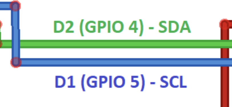
I pointed-out the pin conflict to @zdzislaw (GPIO4 being used in Settings.h for the LED pin and also for the SDA pin) and he’s not responded to that post from me.
Pete.
ropinal
January 18, 2023, 8:18pm
14
En el boceto hay que poner el GPIO4 porque es la salida SDA para el display en modo i2C.
The best option is to define put the GPIO of the pin where you have an LED attached, either the onboard LED, or your own LED plus current limiting resistor.
Pete.
ropinal
January 19, 2023, 9:56am
16
Y cual es número de pin integrado en una placa WEMOS D1??
Which model of Wemos D1?
Pete.
The built-in LED on the Wemos D1 Mini is connected to GPIO2 (the pin labelled D4).
As the D1 Mini only has a Reset button and no Flash button, you’ll need to manually add a push button switch between GPIO0 (the pin labelled D3) and Ground to allow you to clear the provisioned credentials.
You should read this for more info…
There seems to quite a bit of confusion about how the dynamic provisioning process works in the Edgent sketch examples, and how to re-provision a device with new WiFi credentials. Many people omit to configure the board type correctly in the sketch, and this also causes problems.
Here’s a guide to how the process works, and the things to watch out for…
Overview
You start by creating a template, preferably in the web console (https://blynk.cloud/ )
This gives you the BLYNK_TEMPLATE_ID and BLYNK…
Pete.
ropinal
January 20, 2023, 2:06pm
20
Muchas gracias por tu dedicación a nosotros pobres ignorantes.