Okay, here’s a sketch hacked together from segments of my regular (much larger) MQTT sketch.
What it does…
The sketch allows the onboard LED of a NodeMCU (pin GPIO2, active LOW) to be turned on/off by an MQTT message on the Test_Device/LED_Command topic.
The NodeMCU sends-back a confirmation of the LED status on the Test_Device/LED_Status topic.
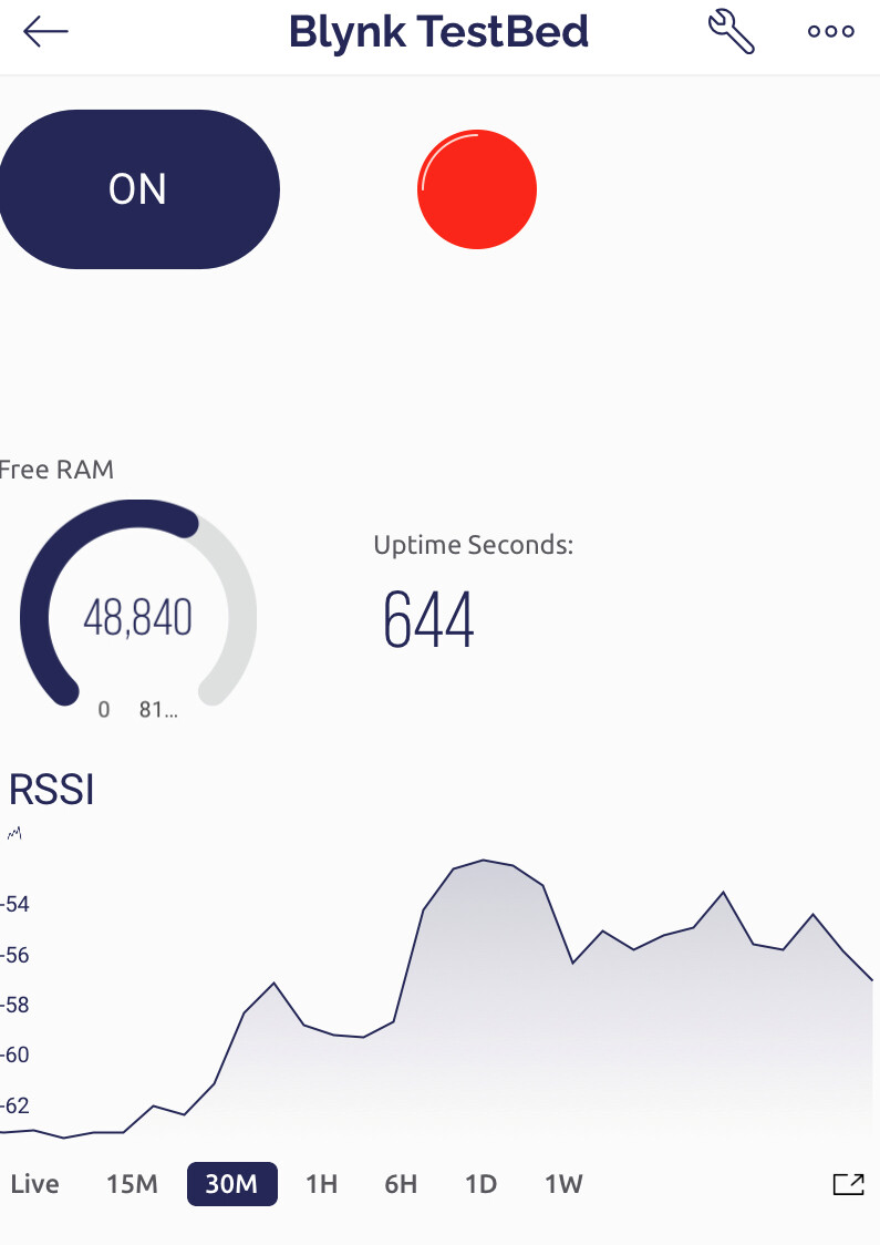
In addition, the NodeMCU publishes it’s RSSI signal strength, Free RAM and Uptime on the Test_Device/RSSI, Test_Device/Free_RAM and Test_Device/Uptime topics once every second.
Here’s the sketch…
#include <ESP8266WiFi.h>
#include <PubSubClient.h>     // https://github.com/knolleary/pubsubclient
#include <SimpleTimer.h>      // Non-blocking timer


// Wi-Fi Credentials...
const char *ssid =                "REDACTED";
const char *pass =                "REDACTED";

// MQTT Server Setting variables...
IPAddress mqtt_server_ip          (xxx,xxx,xxx,xxx);  // IP Address for the MQTT Server...
const int mqtt_port =             1883;               // Port for the MQTT Server...
const char *mqtt_username =       "REDACTED";         // MQTT Server username...
const char *mqtt_password =       "REDACTED";         // MQTT Server password...


// Define WiFi, MQTT & timer objects...
WiFiClient My_WiFi_Client;
PubSubClient MQTTclient(My_WiFi_Client);
SimpleTimer timer;

#define LED_Pin 2       // NodeMCU LED Pin = GPIO2 (Active LOW)


void setup()
{
  Serial.begin(74880);
  pinMode(LED_Pin, OUTPUT);
  digitalWrite(LED_Pin, HIGH);  //Turn the onboard LED Off

  MQTTclient.setServer(mqtt_server_ip, mqtt_port);
  MQTTclient.setCallback(MQTTcallback);           // This function is called automatically whenever a message arrives on a subscribed topic

  Connect_to_WiFi();
  Connect_to_MQTT_and_Subscribe();

  timer.setInterval(1000L, Send_Data);          // Timer to send the RSSI, free memory and uptime data to the MQTT server
  timer.setInterval(30000L, Check_Connections); // Timer to check that we're connected to MQTT
}


void loop()
{
  timer.run();
  MQTTclient.loop();
}


void Connect_to_WiFi()
{
  WiFi.begin(ssid, pass);

  Serial.print("Connecting to WiFi");
  while (WiFi.status() != WL_CONNECTED)
  {
    delay(500);
    Serial.print(".");
  }
  Serial.println();

  Serial.print("Connected, IP address: ");
  Serial.println(WiFi.localIP());
}


void Connect_to_MQTT_and_Subscribe()
{
  Serial.println("Connecting to MQTT...  ");
  // We'll connect with a Retained Last Will (LWT) that updates the 'Test_Device/Status' topic with "Dead" when the device goes offline...
  // Attempt to connect...

  MQTTclient.connect("My_Test_Device", mqtt_username, mqtt_password, "Test_Device/Status",0, 1, "Dead");
  {
    // We get here when the connection attempt was successful...
     MQTTclient.publish("Test_Device/Status","Alive",true); // Update the LWT status to Alive
    Serial.println(F("MQTT Connected"));

    // then we subscribe to the watched topics
    MQTTclient.subscribe("Test_Device/LED_Command");   // Watch the Test_Device/LED_Command topic for incoming MQTT messages
    // Add other watched topics in here...
  }
}


void Check_Connections() // Called with a timer
{
  if(WiFi.status() != WL_CONNECTED)
  {
    Connect_to_WiFi();
  }

  if (!MQTTclient.connected())
  {
    Connect_to_MQTT_and_Subscribe();
  }
}


void Send_Data() // Called with a timer
{
  MQTTclient.publish("Test_Device/RSSI",String(WiFi.RSSI()).c_str(),true);                        // Publish RSSI
  MQTTclient.publish("Test_Device/Free_RAM",String(ESP.getFreeHeap()).c_str(),true);              // Device Free RAM
  MQTTclient.publish("Test_Device/Uptime",String(millis()/1000).c_str(),true);                    // Uptime in seconds
}

void MQTTcallback(char* topic, byte* payload, unsigned int length) // Triggerd whne a message arrives on a subscribed topic
{
  Serial.print("Message arrived [");
  Serial.print(topic);
  Serial.print("] [");
  for (unsigned int i=0;i<length;i++)
  {
    Serial.print((char)payload[i]);
  }
  Serial.println(F("]"));

  String msg_topic = String((char *)topic);
  String msg_payload = String((char *)payload);
  msg_payload.remove(length); // Trim any unwanted characters off the end of the string
  // We now have two string variables, 'msg_topic' and 'msg_payload' that we can use in 'if' statements below...


  // This example shows how to turn a device on and off with a "1" of "0" command on the 'Test_Device/LED_Command' topic
  // Confirmation is echoed-back to Node-Red on the 'Test_Device/LED_Status' topic
  if (msg_topic=="Test_Device/LED_Command")
  {
    SwitchDevice(msg_payload);
  }

  // Handle messages from other topics in here,
  // just like we did with the 'Test_Device/LED_Command' topic above.
  // DON'T FORGET to subscribe to the topic in `Connect_to_MQTT_and_Subscribe()`
}


void SwitchDevice(String power_command) // Called from the MQTT callback
{
  if (power_command=="0") // If this was a power off ("0") instruction then turn the LED off (HIGH)
  {
    digitalWrite(LED_Pin, HIGH);
    MQTTclient.publish("Test_Device/LED_Status","0"); // Feedback confirmation to Node-Red that device is now off
    return;
  }

  if (power_command=="1") // If this was a power on ("1") instruction then turn the LED On (LOW)
  {
    digitalWrite(LED_Pin, LOW);
    MQTTclient.publish("Test_Device/LED_Status","1"); // Feedback confirmation to Node-Red that device is now on
    return;
  }
}
Note that the first field in the MQTTclient.connect command (“My_Test_Device”) is the MQTT Client ID. This MUST be unique for every client device that connects to your MQTT server…
MQTTclient.connect("My_Test_Device", mqtt_username, mqtt_password, "Test_Device/Status",0, 1, "Dead");
The example uses blocking WiFi and MQTT connection commands, but my regular sketch uses non-blocking versions which will put the device into “offline mode” so that physical switches can be used to control devices if WiFi or the MQTT connections havent been established after a set number of attempts.
The example checks the connection status every 30 seconds and re-connects to either WiFi or MQTT if necessary.
As I said earlier, PubSub client uses character variables. The example sketch converts the incoming messages (the subscribed messages which trigger the MQTTcallback function) into strings, so that they can easily be used in if statements.
I’ve left the incoming commands on the Test_Device/LED_Command topic as strings, and used these to turn the LED on and off. This isn’t how I’d normally choose to do things - I’d convert the strings into integers or Boolean variables - but strings can be useful when passing commands that are going to be displayed on LCD or Nextion displays, so I skipped the conversion of the string to an integer in the example.
When publishing data, the values are converted to strings then to char variables using commands like this:
String(millis()/1000).c_str()
A bit messy, but it works!
If the value is already a string then it can be converted to a char variable using:
my_string_variable.c_str()
You can test the functionality using just an MQTT sever (could be a free cloud service) and the MQTT Explorer program.
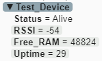
The MQTT Explorer output looks like this:
and if you use MQTT Explorer to publish a “1” to the Test_Device/LED_Command topic you get this:
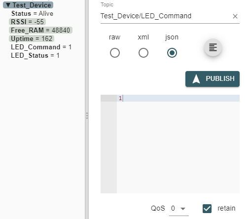
By setting the Retain flag to True, the value is held on the MQTT server, so when the device reboots or re-connects it reads the value and actions it - like an automatic Blynk.sync function.
The serial output looks like this…
Connecting to WiFi.......
Connected, IP address: REDACTED
Connecting to MQTT...
MQTT Connected
Message arrived [Test_Device/LED_Command] [1] << Picks-up the stored ON command
Message arrived [Test_Device/LED_Command] [0] << An OFF command sent via MQTT Explorer
A simple Node-Red flow would look like this:
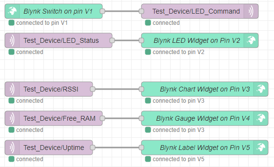
In this part of the above flow, the on/off commands from the Blynk switch widget on pin V1 come in to Node-Red, and are published to the MQTT Test_Device/LED_Command topic, which the device is subscribed to…
![]()
When the device receives that command it turns the physical LED on the board On, and publishes a confirmation Node-Red on the Test_Device/LED_Status topic.
When this confirmation arrives in Node-Red it’s sent to the LED widget on pin V2 like this…
![]()
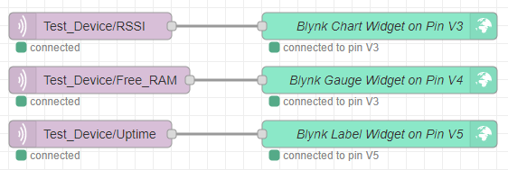
The other three parts of the Node-Red flow just do the same thing with the RSSI, RAM and Uptime values that the device publishes, sending them out to Blynk widgets on V3, V4 and V5…
I made a quick dashboard in the Blynk app, with the switch and LED on V1 and V2, the RAM, Uptime and RSSI as Gauge, Labelled Value and Superchart widgets on pins V4, V5 and V3…
If I wanted to use Node-Red to push other data to the same Blynk dashboard I’d just do the same thing, and that data could come from a totally different device, or some other external source.
Pete.