I am trying to blink virtual LED using Nodemcu Esp8266 generic unit.
Here is sample code written but is not working. let me know if any suggestion. Actually it working well but when i updated IDE i am facing issue. can you suggest me below
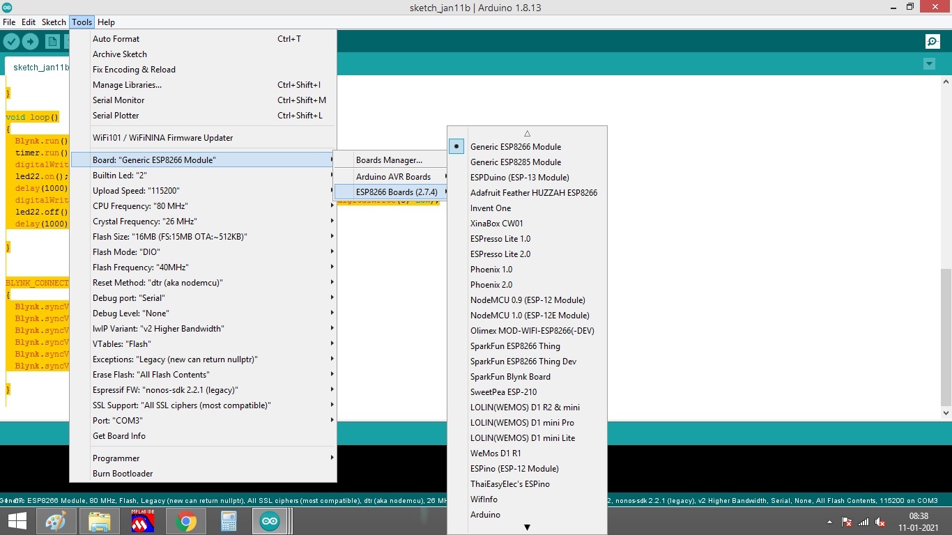
A NodeMCU is not a Generic ESP8266 module, it’s a NodeMCU 0.9 or NodeMCU 1.0
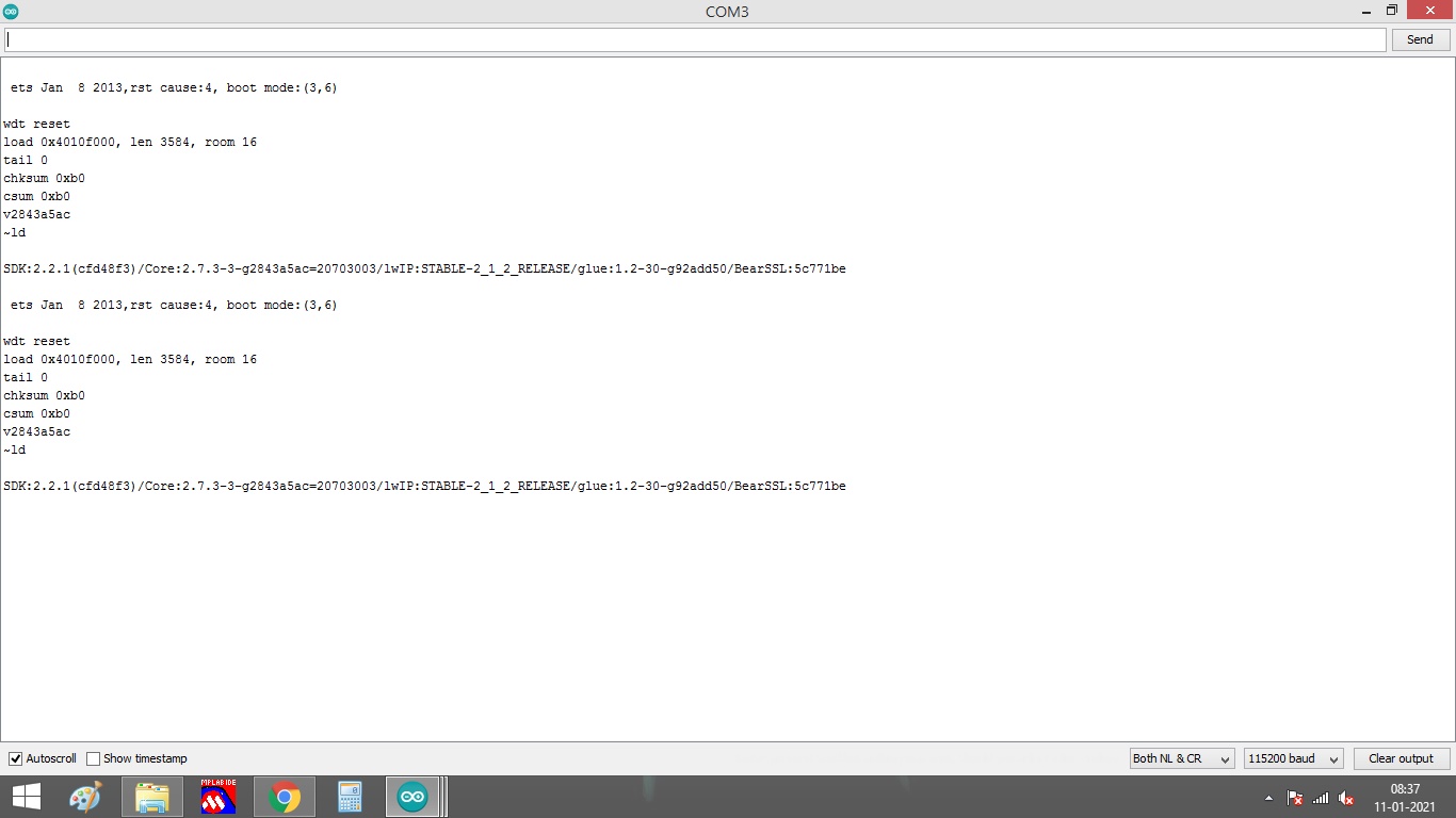
These are GPIO numbers, and GPIO’s 6-11 are special reserved pins. If you attempt to use them in your sketch you will get reboots like the ones in your screenshot. Read this:
Well, you are still using the same problematic GPIO pins, you still have the same messy void loop, except now you’ve commented-out the Blynk.run line that is necessary for Blynk to function.
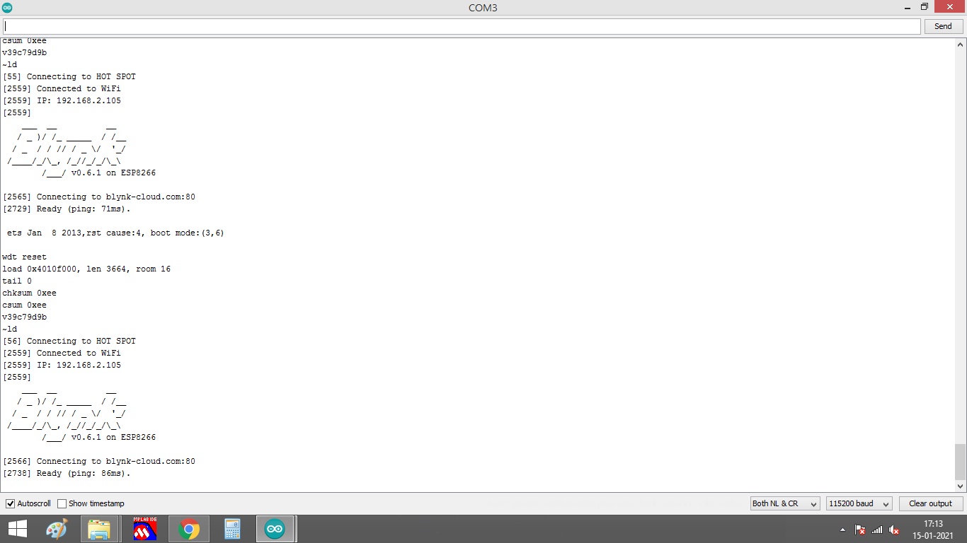
I have made below changes. Now virtual LED started flickering.
I have used only digital pin 4&5
Let me know if d0-d11 are special pin why they mentioned digital io. before IDE got updated i have used same special pins to trigger LED and its working , Now its not working
**Can you suggest me which digital pins i can use.
i need 4 digital output 4 & 5 are used
DS1307 I2c D1 & D2 pins are used . Serial communication
I have used nodemcu AMICA make.
**
Even led are blinking in software in my hardware i could not able to blink LED . I have powered nodemcu using Regulator IC . I have used 560E resistor with 3mm led to gnd w.r.t digital pin
#include"glob.h"
#include <Adafruit_GFX.h>
#include <Adafruit_SSD1306.h>

#define BLYNK_PRINT Serial
#define OLED_RESET LED_BUILTIN  //4
Adafruit_SSD1306 display(OLED_RESET);

#include <ESP8266WiFi.h>
#include <BlynkSimpleEsp8266.h>
#include <WidgetRTC.h>
BlynkTimer timer;
WidgetRTC rtc;  // Set RTC widget.

// You should get Auth Token in the Blynk App.
// Go to the Project Settings (nut icon).

char auth[] = "tI_2ykfiEEbYCZx36gYP5T3NQ_6YMO8T";// COde generated from Blynk
char ssid[] = "HOT SPOT";// user has to set wifi device SSID
char pass[] = "airtel123";// user has to set wifi device Password


const int ledPin =  5;
const int ledPin1 = 4;
//const int ledPin2 =  7;
//const int ledPin3 =  8;

WidgetLED led25(25);
WidgetLED led22(22);
WidgetLED led23(23);
WidgetLED led24(24);


void setup()
{

  Serial.begin(115200);
  Blynk.begin(auth, ssid, pass);
  pinMode(ledPin, OUTPUT);
  pinMode(ledPin1, OUTPUT);
 // pinMode(ledPin2, OUTPUT);
//  pinMode(ledPin3, OUTPUT);
  setSyncInterval(360);

}

void loop()
{
  Blynk.run();
  timer.run();

  digitalWrite(ledPin1, HIGH); digitalWrite(4, HIGH); //digitalWrite(7, HIGH); digitalWrite(8, HIGH);
  Serial.println("LED is on");
  led22.on(); led23.on(); led24.on(); led25.on();
  delay(1000);
  digitalWrite(ledPin1, LOW); digitalWrite(4, LOW); //digitalWrite(7, LOW); digitalWrite(8, LOW);
  led22.off(); led23.off(); led24.off(); led25.off();
   Serial.println("LED is oFF");
   Serial.println(".....................................");
  delay(1000);

}


BLYNK_CONNECTED()
{
  Blynk.syncVirtual(V3); // sync timeinput widget
  Blynk.syncVirtual(V4); // sync timeinput widget
  Blynk.syncVirtual(V5); // sync timeinput widget
  Blynk.syncVirtual(V6); // sync timeinput widget
  Blynk.syncVirtual(V2);
  Blynk.syncVirtual(V50);

}
I have simple code to blink LED . I forget about using SSID and all.
I have tested code with arduino Uno its working well, When i tested with nodemcu its now working
when i measure voltage potential it stays at 1.3v and wont change over I have different Nodemcu unit its doing same thing
If i use serial statement in between its working well. why my led is not changing state Not working #define LED 0
void setup() {
pinMode(LED, OUTPUT);
}
void loop() {
digitalWrite(LED, HIGH);
delay(1000);
digitalWrite(LED, LOW);
delay(1000);
} working
void setup() {
  pinMode(LED_BUILTIN, OUTPUT);     // Initialize the LED_BUILTIN pin as an output
}

// the loop function runs over and over again forever
void loop() {
  digitalWrite(LED_BUILTIN, LOW);   // Turn the LED on (Note that LOW is the voltage level
  // but actually the LED is on; this is because
  // it is active low on the ESP-01)
  delay(1000);                      // Wait for a second
  digitalWrite(LED_BUILTIN, HIGH);  // Turn the LED off by making the voltage HIGH
  delay(2000);                      // Wait for two seconds (to demonstrate the active low LED)
}