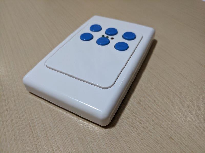
I have built a home automation system based on Blynk comprising a number of sub systems and a master control panel. Phillips Hue lights and Hue hub have recently been added to the mix. One thing that I have been after for years is a wireless (battery operated) push button station for local control (e.g light switching) where a wired power supply would be difficult. I have used 433Mhz key fob type units but they don’t really suit my needs.
My most recent project has been to add battery operated push button stations using nRF24L01 modules. These provide rapid start up, a degree of security, and acknowledgement of receipt of data sent while requiring only a fraction of the power required for WiFi.
The project consists of battery operated push button stations and a central base station that receives messages from the push buttons and communicates with various Blynk projects running on a private Blynk server and the Hue hub server.
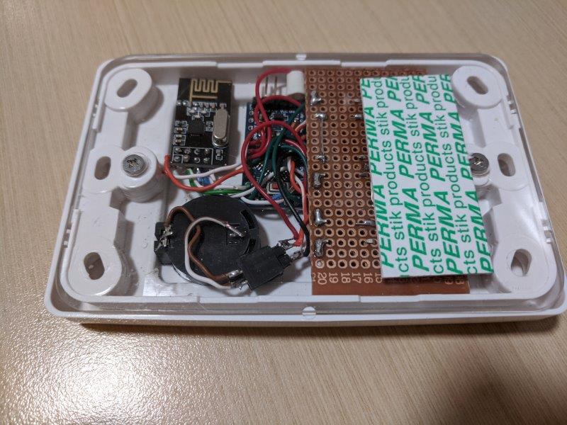
Pictures and .ino’s for the base station and battery operated push button units attached.
The project makes use of some excellent readily available resources:
- pin change interrupt library
- asyncHTTPrequest library
- rocketscream low power library + great advice at www.gammon.com.au
- Phillips Hue developer resources
These sources are referenced in the attached .ino’s
In experimenting with communicating from Blynk systems to the Hue hub server, I found that the standard Arduino HTTP client library was problematic when getting information from the hue server with delays of several seconds occurring at times (it seemed due to blocking while waiting for the server response but there must be more to it which I haven’t tracked down). I had the same problem when I tried using web hooks. Using the asyncHTTPrequest library instead made things work perfectly. The library as developed thus far only provides for GET and POST while for the Hue server I needed GET and PUT. The easy way out was to edit the library files to change POST to PUT.
The sleep mode current draw for the push button units is only 100 nA so battery life will be pretty much limited by self discharge rather than system demand. Using nRF24’s for parts of Blynk based systems in lieu of WiFi links seems to open up a lot of possibilities - and much cheaper than Zigbee.

Button unit code:
/*
Hand held push button station with nRF24L01 for comms to a base station
uP is Arduino Pro Mini 3.3V 8 MHz - also verified that for this application, a 5V 16MHz
Pro Mini works ok on 3V.
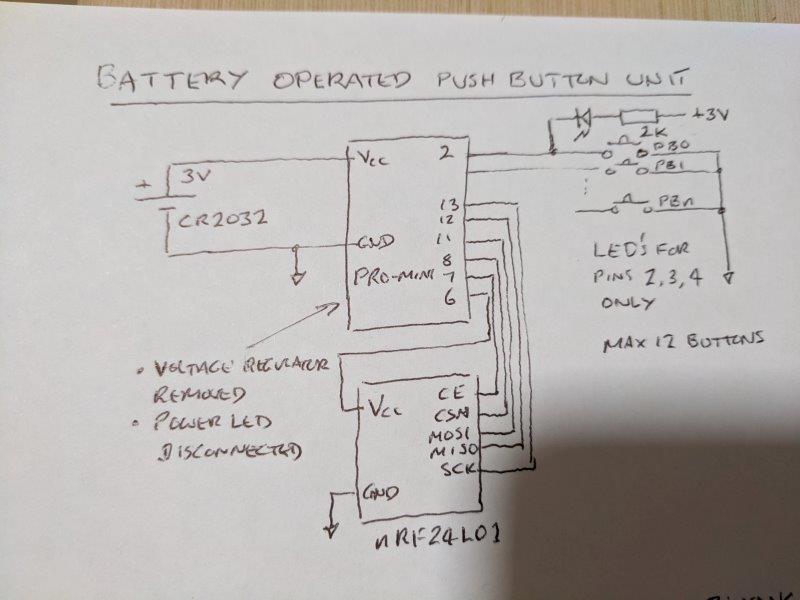
The Pro Mini is modifified by removing the voltage regulator and the power LED dropping resistor.
Each hand held is normally in low power mode. Sleep mode current is around 0.1 uA.
With typical daily usage, battery life will be a function of self leakage rather than mAh's used by the unit.
Battery used is a single lithium CR2032.
Pins 6, 7, 8, 11, 12 and 13 are used for control and communication with the nRF24L01 module.
Pins 2 to 5, 9, 10 and 14 to 19 are available for push buttons which are connected between sensing pins and ground.
Three LED's are connected between Vcc and pins 2, 3 and 4 to provide indication of the success or otherwise of a button press.
To save on pins, dedicated pins are not used for indication - hence when a button connected to pins 2, 3 or 4 is pressed the associated LED will flash briefly
Base station listens for button commands from hand helds and communicates with either a Blynk app,
other Blynk uP's via Blynk bridge or a Hue hub via RESTful based API
There are a maximum of 6 hand helds with one nRF24 pipe per unit
This code is for unit #4
*/
#include <SPI.h> //for communication with nRF24L01 module
#include "RF24.h" //see http://tmrh20.github.io/RF24/
#include "LowPower.h" //see https://www.gammon.com.au/power and https://github.com/rocketscream/Low-Power and http://www.home-automation-community.com/arduino-low-power-how-to-run-atmega328p-for-a-year-on-coin-cell-battery/
#include "PinChangeInterrupt.h" //see https://github.com/NicoHood/PinChangeInterrupt
// Set up the pins to be used for wake up / push buttons
int pins [6] = {2, 3, 4, 5,9,10}; //pins to be used for push buttons - available pins are these plus 14, 15, 16, 17, 18, 19
bool pushbuttons[6]; //state of pushbuttons
byte button = 99; //number of the button that caused the interrupt
byte data[2]; //data to send via nRF24
/****************** User Config ***************************/
// SET THIS TO NUMBER ALLOCATED FOR THE UNIT !!!!!
int unitNumber = 4; //can be in range 1 to 6
#define RF24POWERPIN 6 //Power supply for nRF24 - direct connection of this module to power supply results in excessive sleep power
/* Hardware configuration: Set up nRF24L01 radio on SPI bus plus pins 7 & 8 */
RF24 radio(7, 8); //CE,CSN
/**********************************************************/
//Addresses for the 6 nRF24 pipes
const uint64_t addresses[] = {0x7878787878LL, 0xB3B4B5B6F1LL, 0xB3B4B5B6CDLL, 0xB3B4B5B6A3LL, 0xB3B4B5B60FLL, 0xB3B4B5B605LL };
//interrupt functions
void wakeUp0()
{
button = 0;
}
void wakeUp1()
{
button = 1;
}
void wakeUp2()
{
button = 2;
}
void wakeUp3()
{
button = 3;
}
void wakeUp4()
{
button = 4;
}
void wakeUp5()
{
button = 5;
}
void setup() {
Serial.begin(74880);
Serial.println("Button " + String(unitNumber) + "starting");
pinMode(RF24POWERPIN, INPUT);
// Configure wake up pins as input.
for (int i = 0; i < 6; i++)
{
pinMode(pins[i], INPUT_PULLUP);
}
// Attach the new PinChangeInterrupt and enable event functions
attachPCINT(digitalPinToPCINT(pins[0]), wakeUp0, FALLING);
attachPCINT(digitalPinToPCINT(pins[1]), wakeUp1, FALLING);
attachPCINT(digitalPinToPCINT(pins[2]), wakeUp2, FALLING);
attachPCINT(digitalPinToPCINT(pins[3]), wakeUp3, FALLING);
attachPCINT(digitalPinToPCINT(pins[4]), wakeUp4, FALLING);
attachPCINT(digitalPinToPCINT(pins[5]), wakeUp5, FALLING);
Serial.println("Finishing setup - will now delay for 1 seconds");
delay(1000);
// Now disable the interrupts without losing settings
for (int i = 0; i < 6; i++)
{
disablePinChangeInterrupt(digitalPinToPinChangeInterrupt(pins[i]));
}
}
void loop() {
// Allow wake up pin to trigger interrupt on transition from high to low.
for (int i = 0; i < 6; i++)
{
enablePinChangeInterrupt(digitalPinToPinChangeInterrupt(pins[i]));
}
// Enter power down state with ADC and BOD module disabled.
// Wake up when a wake up pin is low.
LowPower.powerDown(SLEEP_FOREVER, ADC_OFF, BOD_OFF);
// THIS IS THE STARTING POINT AFTER WAKE UP /////////////////////////
// Disable external pin interrupts
for (int i = 0; i < 6; i++)
{
disablePinChangeInterrupt(digitalPinToPinChangeInterrupt(pins[i]));
}
Serial.println("button value = " + String(button));
if (button < 6)Serial.println("Pushbutton on pin " + String(pins[button]) + " pressed");
//Start the nRF24
pinMode(11, OUTPUT); //pin 11 is MOSI which is disabled before sleep to minimise sleep power
RF24Start();
// Prepare data to send
processButtons ();
// Send the data
dataSend();
// Finish off
// Check that all buttons have been released before allowing return to sleep
delay(300);
bool buttonpressed;
long timelast = millis();
bool keeplooping = true;
do
{
buttonpressed = false;
for (int i = 0; i < 6; i++)
{
pushbuttons[i] = !digitalRead(pins[i]);
if (pushbuttons[i])
{
buttonpressed = true;
}
}
if (buttonpressed)timelast = millis();
if (!buttonpressed && (timelast - millis()) > 500)keeplooping = false;
} while (keeplooping);
button = 99;
//CSN pin is left OUTPUT and HIGH at end of process and if left this way causes a drain of 900uA when sleep occurs
//Hence set low and then reconfigure as input before sleep
digitalWrite(8, LOW);
pinMode(8, INPUT);
digitalWrite(11, LOW);//also need to turn off MOSI which is left OUTPUT/HIGH after radio SPI processes
pinMode(11, INPUT);
//Sleep mode power of nRF24 is much greater than slepp mode power for Pro Mini
//Hence power to RF24 is sourced from an output of the Arduino pro mini; turn the power off before sleeping
digitalWrite(RF24POWERPIN, LOW);
pinMode(RF24POWERPIN, INPUT);
} // Loop
void RF24Start()
{
pinMode(RF24POWERPIN, OUTPUT);
digitalWrite(RF24POWERPIN, HIGH);
delay(100);
radio.begin();
radio.powerUp();
radio.setPALevel(RF24_PA_MAX);
Serial.print("PA Level is "); Serial.println(radio.getPALevel());
Serial.print("Is L01+ ? "); Serial.println(radio.isPVariant());
radio.setChannel(76);
Serial.print("Channel is "); Serial.println(radio.getChannel());
Serial.print("Data rate is "); Serial.println(radio.getDataRate());
// Open the writing pipe
radio.openWritingPipe(addresses[unitNumber - 1]);
radio.openReadingPipe(0, addresses[unitNumber - 1]);
radio.startListening();
}
void processButtons ()
{
//TO DO: ADD CODE TO DISTINGUISH BETWEEN SHORT PRESS AND LONG PRESS
boolean pressType = true; //true for short press, false for long press
data[0] = button + 1;
if (pressType) data [1] = 1;
else data [1] = 2;
Serial.print("Data for sending is ");
Serial.print(data[0]);
Serial.println(data[1]);
}
void dataSend()
{
radio.stopListening();
if (!radio.write( &data, sizeof(data) )) {
Serial.println(F("failed"));
pinMode(4, OUTPUT); //signal RED comms fail
digitalWrite(4, LOW);
}
else
{
Serial.println("Button message sent");
if (data[0] < 7)
{
pinMode(2, OUTPUT); //signal GREEN success
digitalWrite(2, LOW);
}
else
{
pinMode(3, OUTPUT); //signal YELLOW invalid button # sent
digitalWrite(3, LOW);
}
}
//CHECK TO SEE IF THE REPEAT SECTION CAN BE DELETED!!!! - currently doesn't work reliably without!
data[0] = 99;
data[1] = 9;
for (int i = 0; i < 1; i++)
{
radio.write( &data, sizeof(data) );
Serial.println("Repeating");
delay(100);
}
delay(100);
radio.startListening();
radio.powerDown();
delay (400);
for(int i=2;i<5;i++) //turn off indication
{
pinMode(i,INPUT_PULLUP);
}
}
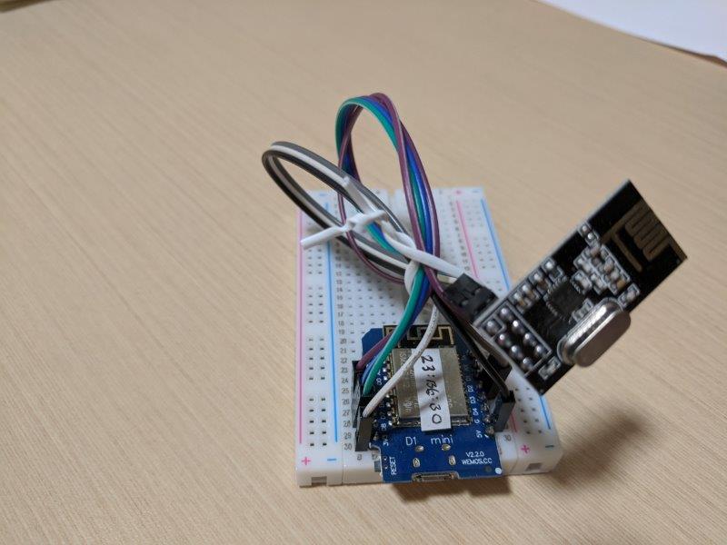
Base station code:
/*

  Base station for nRF24L01 comms with battery powered hand held push button units

  uP is ESP8266 WeMos D1 mini running Blynk

  Base station listens for button commands from hand helds and communicates with either a Blynk app,
    other Blynk uP's via Blynk bridge or a Hue hub via RESTful based API using asyncHTTP

  Each hand held is normally powered down and powers up when a button is pressed. The button press is communicated to the base station
    via nRF24 radio and then the handheld powers down to low power state

  There are a maximum of 6 hand helds with one nRF24 pipe per unit


  WeMos D1 23:B6:B0

  TO DO:
  In Blynk app, allow for selection of which light / function is operated by which handheld / button


*/
#include <SPI.h>  //for communication with nRF24L01 module
#include "RF24.h" //see http://tmrh20.github.io/RF24/

#include <ESP8266WiFi.h>
#include <asyncHTTPrequest.h> //see https://github.com/boblemaire/asyncHTTPrequest and https://github.com/boblemaire/asyncHTTPrequest/wiki/
//source asyncHTTPrequest.h and asyncHTTPrequest.cpp files edited to change POST to PUT
asyncHTTPrequest request;

//*** OTA STUFF *****
#include <ESP8266mDNS.h>
#include <WiFiUdp.h>
#include <ArduinoOTA.h>

//**** LAN and Blynk local server details ********
char ssid[] = "network name";
char pass[] = "password";
char ip[] = "local blynk server ip address";

//**** BLYNK STUFF *******
//#define BLYNK_DEBUG
//#define BLYNK_PRINT Serial
#define BLYNK_NO_BUILTIN   // Disable built-in analog & digital pin operations
#define BLYNK_NO_FLOAT     // Disable float operations
#define BLYNK_MSG_LIMIT      60 // this parameter can have a critical affect on performance! too low and loops/sec can be greatly reduced
// default is 20 and is ok for this application; 60 can be required to avoid impact on speed for more Blynk intensive applications
#include <BlynkSimpleEsp8266.h>
char auth[] = "Blynk project ID"; //Blynk project ID
BlynkTimer timer;
WidgetBridge bridge1(V91);//to Blynk master control panel
WidgetBridge bridge16(V106); //to Lights Circuit 7 controller

/****************** User Config ***************************/

/* Hardware configuration: Set up nRF24L01 radio on SPI bus plus pins 4 & 5 */
RF24 radio(4, 5); //CE, CSN for ESP8266
//RF24 radio(7, 8); //CE, CSN for Arduino Nano
/**********************************************************/

//Addresses for the 6 nRF24 pipes
const uint64_t addresses[] = {0x7878787878LL, 0xB3B4B5B6F1LL, 0xB3B4B5B6CDLL, 0xB3B4B5B6A3LL, 0xB3B4B5B60FLL, 0xB3B4B5B605LL };

byte message[4]; //nRF24 payload
bool newMessage = false; //new payload received

//Strings for sending requests to Hue hub
String hue_http_header;
String hue_http_body;

String hue_user_name = "hue user name";
String hue_address = "http://hue hub LAN ip address/api/";
String hue_lights = "/lights/";
String hue_state = "/state";
String hue_groups = "/groups/";
String hue_action = "/action";
String hue_sensors = "/sensors/";

//***** FOR PARSING JSON RECEIVED FROM HUE HUB ******
#include <ArduinoJson.h>  //https://arduinojson.org/
DynamicJsonDocument doc(1024); //holds parsing results


bool CBavailable; //asyncHTTPrequest call back available (response received from server)
String CBreturn;  //return message from Hue hub server
bool httpType; //type of HTTP request to be processed by asyncHTTPrequest - true=GET, false=PUT

//variables for Hue hub interface
bool toggling;
bool groupState;
bool lightState;
int putItemId;
bool putItemType; //true=light, false=group

// asyncHTTPrequest send function
void sendRequest() {
  if (request.readyState() == 0 || request.readyState() == 4) {
    if (httpType)
    {
      request.open("GET", hue_http_header .c_str());
      request.send();
    }
    else
    {
      request.open("PUT", hue_http_header .c_str());
      request.send(hue_http_body );
    }
  }
}

// asyncHTTPrequest call back function - executed when there is an async call back (server response received)
void requestCB(void* optParm, asyncHTTPrequest* request, int readyState) {
  if (readyState == 4) {
    CBreturn = request->responseText();
    Serial.println( CBreturn);
    Serial.println();
    CBavailable = true;
    request->setDebug(false);
  }
}


void setup() {

  Serial.begin(74880);  //this speed is convenient as it matches that used by the ESP8266 debug messaging
  hue_http_header.reserve (100); //URL
  hue_http_body.reserve (100); //Body
  CBreturn.reserve (800); //return body from hue

  ArduinoOTA.begin();
  Blynk.begin(auth, ssid, pass, ip, 8080);

  Serial.println(F("RF24 base station starting"));

  radio.begin();
  radio.setPALevel(RF24_PA_MAX);

  // Open a reading pipe for each of 6 hand helds
  for (int i = 0; i < 6; i++)
  {
    radio.openReadingPipe(i, addresses[i]);
  }

  // Start the radio listening for data
  radio.startListening();
  Serial.print("PA Level is "); Serial.println(radio.getPALevel());
  Serial.print("Is L01+ ? "); Serial.println(radio.isPVariant());
  Serial.print("Channel is "); Serial.println(radio.getChannel());
  Serial.print("Data rate is "); Serial.println(radio.getDataRate());

  timer.setInterval(100L, handleRF24);  //

  request.setDebug(true);
  request.onReadyStateChange(requestCB);

}

void loop() {
  ArduinoOTA.handle();
  Blynk.run();
  timer.run();

  /************** handle message ***********************/

  if (newMessage)
  {
    handleMessage();
  }

  if (CBavailable)
  {
    handleCBreturn();
  }

  yield();
} // Loop

void handleRF24()
{
  uint8_t pipeNum;
  byte data[2];

  if (radio.available(&pipeNum)) {
    radio.read(&data, sizeof(data));
    Serial.print("Got data on pipe");
    Serial.println(pipeNum);
    message[0] = pipeNum; //which push button station sent the message? (range is 0 to 5)
    message[1] = data[0]; //which button was pressed?
    message[2] = data[1]; //short press or long press?
    Serial.println("Station Number " + String(message[0]) +  "Button Type " + String(message[1]) + " Press type " + String(message[2]));
    if (message[1] < 99) newMessage = true;
  }
}

void handleMessage()
{
  switch (message[0])
  {
    case 1: //HANDLE CASES 1 THRU 12 for 12 button hand held unit #2
      switch (message[1])
      {
        case 1: //toggle selected light; 3=kitchen
          toggleLight(3);
          break;
        case 2: //increase selected light
          increaseLight(3, 50);
          break;
        case 3: //decrease selected light
          increaseLight(3, -50);
          break;
        case 4: //toggle selected light; 14=family south
          toggleLight(14);
          break;
        case 5: //increase selected light
          increaseLight(14, 50);
          break;
        case 6: //decrease selected light
          increaseLight(14, -50);
          break;
        case 7: //toggle selected light
          toggleLight(4);
          break;
        case 8: //increase selected light
          increaseLight(4, 50);
          break;
        case 9: //decrease selected light
          increaseLight(4, -50);
          break;
        case 10: //toggle selected light
          toggleLight(5);
          break;
        case 11: //increase selected light
          increaseLight(5, 50);
          break;
        case 12: //decrease selected light
          increaseLight(5, -50);
          break;
        default:
          break;
      }
      break;

    case 2: //4 button hand held unit #3
      switch (message[1])
      {
        case 1: //
          toggleLight(3);
          break;
        case 2: //
          toggleLight(14);
          break;
        case 3: //
          toggleLight(4);
          break;
        case 4: //
          toggleLight(5);
          break;
        default:
          break;
      }
      break;

    case 3: //4 button hand held unit #4
      switch (message[1])
      {
        case 1: //
          bridge16.virtualWrite(V0, 1);
          break;
        case 2: //
          bridge16.virtualWrite(V1, 1);
          break;
        case 3: //
          bridge16.virtualWrite(V49, 1);
          break;
        case 4: //
          bridge16.virtualWrite(V48, 1);
          break;
        case 5: //
          toggleLight(4);
          break;
        case 6: //
          toggleLight(5);
          break;

        default:
          break;
      }
      break;
    default:
      break;
  }
  Serial.println("Message handled");
  newMessage = false;
  for (int i = 0; i < 3; i++)
  {
    message[i] = 9;
  }

}

BLYNK_CONNECTED() {

  bridge1.setAuthToken("blynk project ID");//master
  bridge16.setAuthToken("blynk project ID"); //to Lights Circuit 7 controller

}

// Program for toggling a hue light- a GET request is sent to get the current light state
// The handleCBreturn() function then carries out a PUT request to chnage the lighht to the opposite state

void toggleLight(int lightNumber)
{
  putItemType = true; //it's a light, not a group
  putItemId = lightNumber;
  toggling = true;
  httpType = true; //it's a GET to get light current state
  hue_http_header  = hue_address + hue_user_name + hue_lights + String(putItemId);
  sendRequest();
}

// Program for changing the illumination level of a hue light by a specified increment - increment can be negative

void increaseLight(int lightNumber, int increment)
{
  putItemType = true; //it's a light, not a group
  putItemId = lightNumber;
  toggling = false;
  httpType = false; //it's a PUT to change brightness level
  hue_http_header  = hue_address + hue_user_name + hue_lights + String(putItemId) + hue_state;
  hue_http_body  = "{\"transitiontime\": 9, \"bri_inc\":" + String(increment) + "}";
  sendRequest();
}

// Program for handling the response from the hue hub server

void handleCBreturn()
{
  bool itemState;
  Serial.println("Call back return");
  Serial.println( CBreturn);
  if (toggling && putItemType)
  //if we are toggling a light, extract the first part of the JSON that contains the current light state
  //if we are toggling a group, the hue response is much shorter, hence no need to extract before deserialising
  {
    int first = CBreturn.indexOf(':') + 1;
    int last = CBreturn.indexOf('}') + 1;
    CBreturn = CBreturn.substring(first, last);
  }
  Serial.println( CBreturn);
  DeserializationError err = deserializeJson(doc,  CBreturn);
  if (err) {
    Serial.print(F("deserializeJson() failed with code "));
    Serial.println(err.c_str());
  }
  else
  {
    if (toggling)
    {
      toggling = false;
      if (putItemType)
      {
        itemState = doc["on"];
        hue_http_header  = hue_address + hue_user_name + hue_lights + String(putItemId) + hue_state;
      }
      else
      {
        itemState = doc["action"]["on"];
        hue_http_header  = hue_address + hue_user_name + hue_groups + String(putItemId) + hue_action;
      }
      if (itemState)
      {
        hue_http_body  = "{\"on\": false}";
      }
      else
      {
        hue_http_body  = "{\"on\": true,\"bri\": 150} ";
      }
      httpType = false; //We now want to PUT the change of state
      CBavailable = false;
      CBreturn = " ";
      sendRequest();
    }
  }
  CBavailable = false;
  CBreturn = " ";
}