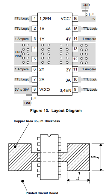
This was my very first project. Most projects I could easily find involved 2 or 4 dc motors. I looked around and founds codes that fit my purposes and modified it. The biggest headache came with the L293D driver. The left side of the IC seemed to not work in both directions(but I hadn’t connected ALL grounds of the IC on these tries), maybe to a fault of my own or maybe it is specd out like this(something about a quadruple half bridge)~ Also to make the IC work as intended I had to wire up all the grounds(jumping them should help clean things up), most tutorials/instructions call for one; at most two grounds on opposite sides. The original code included a V1 slider to control speed, I did not need this for my project.
#include <Servo.h> //disables PWM on pins 9&10 for Arduino nano
#define BLYNK_PRINT Serial
#include <ESP8266_Lib.h>
#include <BlynkSimpleShieldEsp8266.h>
#include <SoftwareSerial.h>

SoftwareSerial EspSerial(2, 3); // RX/TX
#define ESP8266_BAUD 9600 //define Esp baud rate

ESP8266 wifi(&EspSerial);
Servo myServo;
// You should get Auth Token in the Blynk App.
// Go to the Project Settings (nut icon).
char auth[] = "Your Blynk Auth Token";
// Your WiFi credentials.
// Set password to "" for open networks.
char ssid[] = "Your network name here";
char pass[] = "Your wifi password here";

const int enable1 = 11; // Enable pin 1
const int Forward = 7; //Forward
const int Backward = 8; //Reverse
const int servo = 6; //servo

 int speed = 0; //
/*BLYNK_WRITE(V1)
{


  speed = param.asInt();
  Serial.println(speed);
  analogWrite(enable1, speed);
}*/

BLYNK_WRITE(V2)
{
  int x = param[0].asInt();
  int y = param[1].asInt();


  Serial.println(" X = ");
  Serial.print(x);
  Serial.print(" ; Y = ");
  Serial.println(y);

   if ( y > 200)
   {
    analogWrite(enable1, 255);
    digitalWrite(Forward, HIGH);
    digitalWrite(Backward, LOW);
   }

   else if ( y < 50)
   {
      analogWrite(enable1, 255);
      digitalWrite(Backward, HIGH);
      digitalWrite(Forward, LOW);
   }


   else
    {
      digitalWrite(enable1, LOW);
      digitalWrite(Backward, HIGH);
      digitalWrite(Forward,HIGH);
    }
    int angle = 0;//
    angle = param[0].asInt();
    if (angle >= 168)
      angle = 180;
    else if (angle <= 16)
      angle = 0;
      else
      angle = 90;

   myServo.write(angle);
  }

  void setup() {

    pinMode(enable1, OUTPUT);
    pinMode(Forward, OUTPUT);
    pinMode(Backward, OUTPUT);
  //  digitalWrite(enable1,HIGH);

    // Debug console
    Serial.begin(9600); //debug console
    //Set ESP8266 BAUD RATE
    EspSerial.begin(ESP8266_BAUD);
    delay(10);

    Blynk.begin(auth, wifi, ssid, pass);

 myServo.attach(servo);
  }

  void loop() {
    Blynk.run();
  }