Hey guys,
Sorry but I had some stupid questions which I can not solve themselfe. It´s naturally about Blynk 
And yes… I read the documents but there I did not find any solutions, and until now I did not find any similar project but I am sure that there must be a lot.
To my project: I want control a normal LED-strip (no neopixel or something other) with a Wemos D1 mini and my smartphone. First of al I want know how to control a physical “normal” LED. (digitalWrite (pin, value) Blynk do not like or?? After I solved this, I want know also how to get out an analog signal from the wemos which I adjust in Blynk App with a slider. So I would dim the led. Exist also a way to fade up and down a LED automatically when for example a timer it says.
Thanks
Kind regards
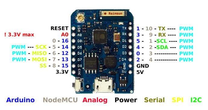
Are you aware that the labels on that board mean absolutely nothing i.e. they are not the pins you would use in a sketch.
So take the label D1, it is not “pin” 1 it is (GPIO) pin 5
Yeah thanks, but as far as this I am just…  I am still conrolling the temperature and the humidity with a DHT22. Now I want build up my “Blynk Projekct interface” with some buttons and sliders to controll with them the illumination in my room. So now I am focused how to handle whith virtual Pins which give me the values I want output on my D1 mini.
Bould you please help me? 
Have you controlled a physical LED via Blynk with direct pin access before you moved on to virtual pins?
Yes… All over the place ![]()
It is a basic case of “LEGO” block programming, combining Blynk commands and Arduino commands, and paying attention to the differing pin layouts of boards vs code expectations.
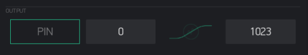
BLYNK_WRITE(V0)  // Runs when slider widget (on V0) is moved.  Set limits 0-1023 for ESP
{
  brightness = param.asInt();  // Get slider value.
  analogWrite(5, brightness);  // Send slider value to real LED on any PWM capable pin on your board
}
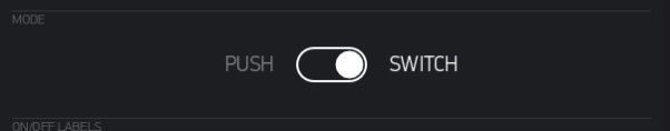
For LED on / off pick Button widget and set in SWITCH mode set to use V0:
BLYNK_WRITE(V0){
  if(param.asInt()){
    digitalWrite(pin, 1);
  }
  else{
    digitalWrite(pin, 0);
  }
}
WTF and that was it all 
Why at the hell I did not find out alone. 
And let my guess:
And to control a LED which is connected on D1 on my wemos with a slider which I set to V1 I write
BLYNK_WRITE(V1){
  if(param.asInt()){
    analogeWrite(D1, value);
  }
  else{
    digitalWrite(D1, 0);
  }
}
But where I say that the variable (value) I get from slider V1?
I mean the declaration that the value I get from slider is the output value from wemos… And works it with fadeing up and down?
Thanks in the meantime
Don’t use D1 in your sketches, it is simply 5.
That would be the param.asInt as in “Parameter and integer” Which with a Button will default as 0 or 1 and chosen via the if() command. so you don’r need to also put that in your digitalWrite
Thus for a simple ON/OF with button
BLYNK_WRITE(V1){  // Get button widget value
  if(param.asInt()){  // If value is 1 run this command
    digitalWrite(5, HIGH);
  }
  else{ // If value is 0 run this command
    digitalWrite(5, LOW);
  }
}
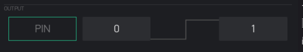
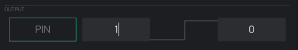
Note that ESP’s sometimes have pins with pull up or pull-down resistors, so if the opposite action happens, then just re code as required with your digitalWrite, or change the settings in the widget. i.e instead of 0-1 use 1-0
And the same goes for the Slider but with a different Arduino command (analogWrite) for sending PWM signals to the pin
Hey Gunner, sorry for my gaucheness but it will not work… Now I tried anything. I tried an other Wemos d1 Mini, I uploaded old sketches to check the functional efficiency from Wemos D1 mini… Nothing, the LED do not light. 
I modified the sketch you send me now a little bit to see what happens.
In Serial Monitor I get the values 1 and 0 if I press the button on Blynk App but I do not get any output signal from Wemos D1 mini. What I am doing wrong?
Here my code:
#define BLYNK_PRINT Serial
#include <ESP8266WiFi.h>
#include <BlynkSimpleEsp8266.h>

char auth[] = "b5a2426a237549448f9dff83a354xxxx";
char ssid[] = "Fritzboxxxxx"
char pass[] = "6703370948621811xxxx";

BLYNK_WRITE(V1)
{
  int pinValue = param.asInt(); // assigning incoming value from pin V1 to a variable
  if (pinValue == 1) {                 // If value is 1 run this command
    digitalWrite(5, HIGH);          //D1 output from Wemos D1 mini
  }
  else {                                     // If value is 0 run this command
    digitalWrite(5, LOW);          //D1 output from Wemos D1 mini
  }
  Serial.print("V1 Button value is: ");
  Serial.println(pinValue);
}

void setup()
{
  Serial.begin(9600);
  Blynk.begin(auth, ssid, pass);
}

void loop()
{
  Blynk.run();
}
![Screenshot_20180218-173109[1]](https://community.blynk.cc/uploads/default/original/2X/9/9856e5795d62a73d659f3b9785da195d8b373e7a.png)
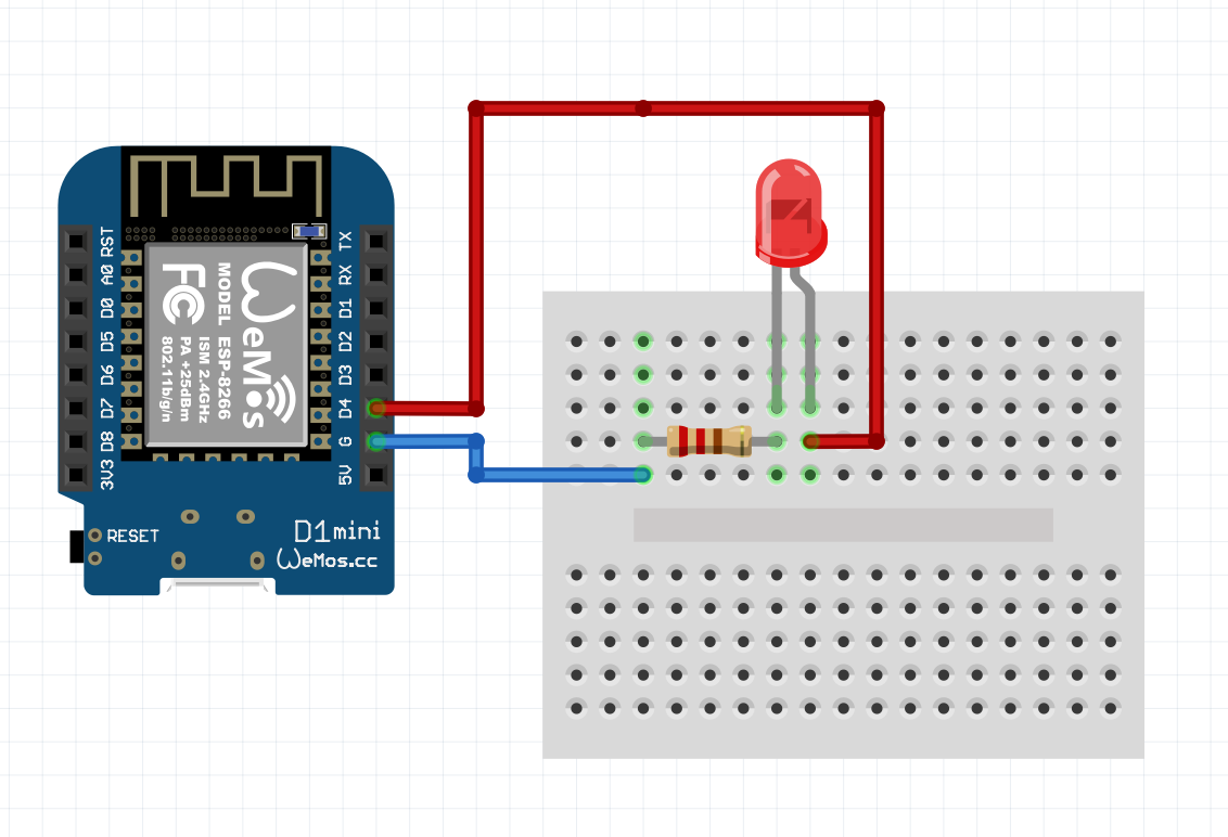
Your code seems OK and you are getting the serial prints, so the issue must be your wiring to the LED. Comfirm you have it the correct way around ( long lead to +) between D1 (Arduino 5) and short lead to either GND or 3.3v… Depending on how you want to use the digital pin, as source or sink respectively.
For testing, you can also use D4 (Arduino 2) without any wiring as that pin is connected to the internal LED.
No success, I do not know why but now the led light usually. It lie usually against 2,45V which I meassured with an multimeter, equal if I push the button in the app or not. The same happens with my other Wemos D1 mini. If I connect the LED with ground and D4 it shines because on the output I usually measure 2,45V
Try this
Nothing…no internal led light

Look here and try that non-blynk LED flashing code…
It’s not working because
pinMode(5, OUTPUT); // sets the digital pin 5 as output
is missing from void setup()
Pete.
Good catch!! That’s one reason I “normally” stay away form forum use on the phone… too easy to miss little details on little screen 