Olá a todos.
Alguém sabe me dizer porque estou conectado no servidor blynk, recebo as mudanças dos valores de V0, ou pino virtual V0, que ´mostro no Serial.print, porém não liga o LED da placa.
Meu código:
[Unformatted code removed by moderator]
Olá a todos.
Alguém sabe me dizer porque estou conectado no servidor blynk, recebo as mudanças dos valores de V0, ou pino virtual V0, que ´mostro no Serial.print, porém não liga o LED da placa.
Meu código:
[Unformatted code removed by moderator]
please edit your post, using the pencil icon at the bottom, and add triple backticks at the beginning and end of your code so that it displays correctly. Triple backticks look like this: ```
@Andre_De_Souza_Marti Please edit your post, using the pencil icon at the bottom, and add triple backticks at the beginning and end of your code so that it displays correctly.
Triple backticks look like this:
```
Copy and paste these if you can’t find the correct symbol on your keyboard.
Pete.
You’d better throw your Atmega into the bin and buy a NodeMCU ![]()
Thanks for answering. We in this field are stubborn and are unhappy with certain behaviors in our projects. Therefore, I would be very grateful if you could provide any clarification.
The problem is that if I upload it to ATMega with a simple code, I manipulate the board’s led, but with Blynk, with the upload to ESP, the board’s led does not light up despite Serial.print, showing that the values of V0, they are coming.
Thak You.
Apparently, you’ve had a problem too…
@Andre_De_Souza_Marti you need to start by posting your code in a useable format. That means posting it as text, not a screenshot, and placing triple backticks on a separate line at the beginning and end of your code.
You should also provide as much information as possible about your project, including the datastreams you’ve created, and the widgets you’ve linked to these datastreams.
Pete.
Let’s go. Sorry for the manner, but I’m going to improve my communication here. I used this same board with the old version of blynk, I used the EspDuino board (Esp 13 Module), but with the new version, I only got it with the NodeMcu. Here’s my code on BlynkEdgent:
#define BLYNK_TEMPLATE_ID "my template"
#define BLYNK_TEMPLATE_NAME "ATMega2560"


#define BLYNK_FIRMWARE_VERSION        "0.1.0"

#define BLYNK_PRINT Serial
//#define BLYNK_DEBUG

#define APP_DEBUG

// Uncomment your board, or configure a custom board in Settings.h
//#define USE_SPARKFUN_BLYNK_BOARD
#define USE_NODE_MCU_BOARD
//#define USE_WITTY_CLOUD_BOARD
//#define USE_WEMOS_D1_MINI

#include "BlynkEdgent.h"
//BLYNK_CONNECTED()
//{
//  Blynk.syncVirtual(V0);
//}
void setup()
{
  pinMode(13,OUTPUT);
  Serial.begin(115200);
  BlynkEdgent.begin();
}
  BLYNK_WRITE(V0)
  {
    Serial.print("Valor de V0: ");
    Serial.println(param.asInt());
    if(param.asInt() == 1)
    {
      digitalWrite(13,HIGH);
    }
    else
    {
      digitalWrite(13,LOW);
    }
  }

void loop()
{
  BlynkEdgent.run();
}
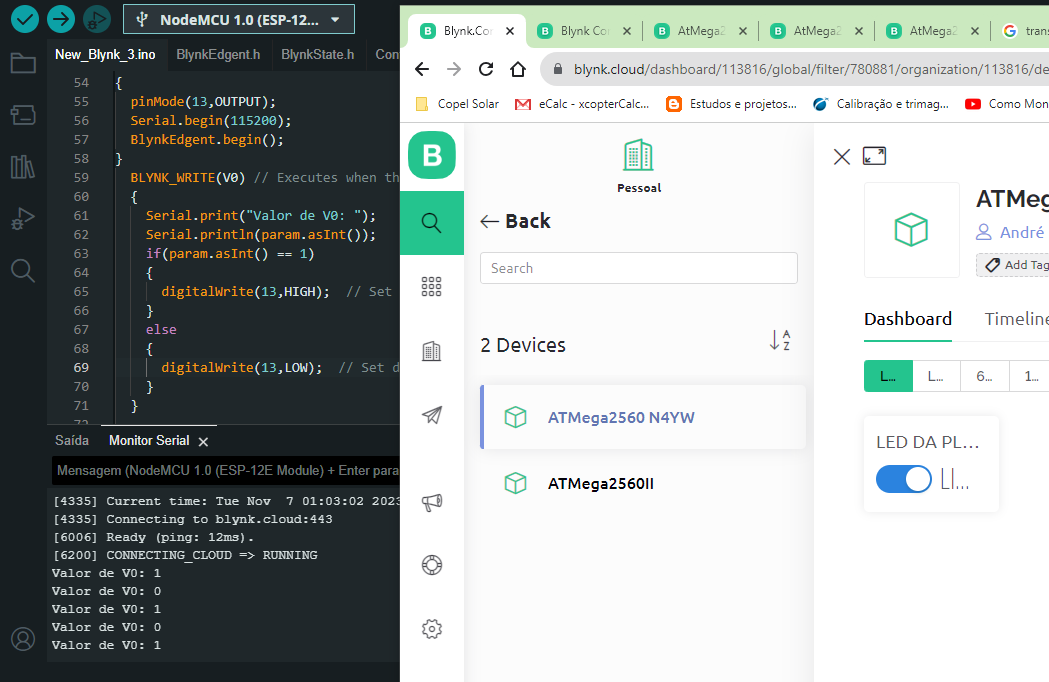
The data flow is basic, just establish again the possibility of manipulating the ports remotely, I am sending via the App or via the Web, a variable of the integer type, which can be 0 or 1, on virtual pin 0. I can verify this variable being changed either via App or Web via the serial monitor, however, the board’s LED is not responding.
Once again, you’ve posted code without triple backticks.
Pete.
Pete,
Edited.
Thanks.
Are you trying to switch the NodeMCU’s onboard LED, or do you have an LED and a current limiting resistor connected between GPIO13 (Pin D7) and GND?
The onboard LED on a NodeMCU is normally connected to GPIO2.
If you’re using Edgent then then the GPIO2 LED will normally be used as the Edgent indicator LED.
Is there a reason why you’ve switched to Edgent?
Pete.
So, I’m trying to turn on the board’s integrated LED, but the board is an ATMega 2560+wifi esp8266. I’m using the NodeMcu configuration, simply because it’s the only one I was able to connect. As for using Edgent, it doesn’t matter, because the connection using Token, I have the same problem. I go online, I can see the V0 value on the serial monitor, but the integrated LED does not work. I tried other digital ports by connecting a relay module, which also did not activate.
Okay, that wasn’t clear from what you wrote previously.
Is there any reason why you are using this board instead of something more mainstream?
What is your ultimate project, and how many GPIO and Analog pins do you need?
Edgent makes the whole thing far more complex, and introduces opportunities for pin conflicts as well.
I’d stick with static provisioning initially.
If the board you are using is the one with the DIP switches on it then I think that all you are doing at the moment is running your code on the ESP8266. When you do this, you can’t talk to any of the GPIOs on the Mega board. To use this board with Blynk you’ll need to find and upload the factory AT firmware to the onboard ESP8266 (which you’ve overwritten by uploading a sketch to the ESP8266) then run code designed for the Mega/Uno with an ESP-01 style AT modem.
When you do this, you won’t be able to use Edgent with the Mega, as dynamic provisioning and Blynk.Air aren’t supported with this setup.
You could look at running Blynk NCP on this hardware, it may be a better solution, but TBH I’d probably do as @Blynk_Coeur said and throw the board in the bin and use a more appropriate board instead.
Pete.
Disappointing, because I was already using this same board with blink in the old version, and any digital port would light up the internal LED, using two relays and a servo and a temperature sensor circuit. From the moment I could no longer log into Blynk and had to update the App, I came across this situation.
André.
And what sketch were you using on Blynk Legacy?
Pete.
An ESP32 costs less than $6 ![]()
The cost of an ESP32 is somewhat irrelevent if the OP has a mega / ESP combined board and wants to use it. There are benefits to linking a MEGA to, say, an ESP8266 like a serious number of IO pins, 5 v IO’s, a useful number of ADC’s, Easily fitted GLCD displays, many shields etc. I do appreciate that those combined boards are not the greatest and Uno’s Mega’s are ‘old hat’ but the ESP32 in all its guises is not a panacea for all evils!
One point of note is that the ESP devices on the combo boards are not nodeMCU’s they are the basic ESP8266 chip with the necessary resistors, caps etc.
I have moved from the old version of Blynk, that I ran on a local server, to BlynkIOT without a lot of issues. There is a bit of learning to do but the BlynkIOT documents / examples are good. I do not use Edgent, as for me it has no benefits. I would advise you to scrap Edgent and just set up a Basic Blynk sketch so that you can make sure it connects to Blynk first. Then you work on the linkage from ESP device to the Mega. I use ESP32 / 8266’s connected to Uno, Pro Mini or Mega boards quite a lot because I have a lot them!!
Peter and others are right to advise you to use more modern / widely supported boards appropriate to a particular project but I can see no reason why, if your project worked on the old Blynk, it shouldn’t work with the new version as it doesn’t sound overly complex. I really like BlynkIOT and find it easy to use. Good luck.
The OP has gone quiet, I guess because they have realised their mistake.
I assume that instead of uploading the sketch to the Mega, as they did with their Legacy sketch, they’ve uploaded it to the ESP8266 and overwritten the factory AT firmware.
Recovering from this mistake I’d do-able, but much more hassle than simply uploading a new sketch, especially if your knowledge of MCUs is limited.
I agree that there are situations where an Uno/Mega has some advantages over more modern boards, but most people fall for the sales hype and think that these are a better board, rather than evaluating the available boards and choosing the best one for their situation.
I think the Blynk NCP system is a much better approach with these boards though, but it needs more step-by-step tutorials for boards like this one, so newcomers can quickly get up and running.
Pete.
Hi Peter, I agree. I am not familiar with the Blynk NCP system so I can’t comment on that, I’ll have a look at it. I seem to recall that when I evaluated the combo board I ditched the AT command set up and used something like the SerialTransfer library to link ESP8266 and the Mega. I must confess that I like hanging ESP8266 boards onto non WiFi boards. One usage case is in mains AC current monitoring using CT’s and the brilliant Emon library, the Arduino Uno, Mega and mini boards are very good for that application(multiple ADC’s). The linked ESP device can then send data to BlynkIOT, Happy days! The ESP32 can also run a cloned version of the Emon library and it gives acceptable results. When I get time I think I’ll try one of the combo boards I have with BlynkIOT and see how I get on.