Hello, I installed Blynk, added a few sensors (temp/humidity…) everything worked and I am really happy with it, so thank you for this great app!
Now I have a problem: I want to connect a pH Sensor via the pH Circuit Board by Atlas Scientific which works with the sample I2C sketch.
Because I have no wifi/ethernet shield, my Arduino is connected via USB to my PC. To get sensor readings I need the serial monitor to send commands (for example “r” to take a single reading).
When I try to combine the Atlas sketch with your Arduino_Serial_USB sketch, I run into the problem that I can’t use the serial monitor when the blynk-ser.bat is running on my PC.
//**THIS CODE WILL WORK ON ANY ARDUINO**
//This code has intentionally has been written to be overly lengthy and includes unnecessary steps.
//Many parts of this code can be truncated. This code was written to be easy to understand.
//Code efficiency was not considered. Modify this code as you see fit.
//This code will output data to the Arduino serial monitor. Type commands into the Arduino serial monitor to control the EZO pH Circuit in I2C mode.
//this code was last updated 7-25-2016


#include <Wire.h>                //enable I2C.
#define address 99               //default I2C ID number for EZO pH Circuit.


char computerdata[20]; //we make a 20 byte character array to hold coming data from a  pc/mac/other.

byte received_from_computer = 0; //we need to know how many characters have been received.

byte code = 0;                   //used to hold the I2C response code.
char ph_data[20];                //we make a 20 byte character array to hold incoming data from the pH circuit.

byte in_char = 0;                //used as a 1 byte buffer to store in bound bytes from the pH Circuit.
byte i = 0;                      //counter used for ph_data array.
int time_ = 1800;                //used to change the delay needed depending on the command sent to the EZO Class pH Circuit.

float ph_float;                  //float var used to hold the float value of the pH.


void setup()                    //hardware initialization.
{
  Serial.begin(9600);           //enable serial port.
  Wire.begin();                 //enable I2C port.
}


void loop() {                   //the main loop.

  if (Serial.available() > 0) {  //if data is holding in the serial buffer
    received_from_computer = Serial.readBytesUntil(13, computerdata, 20); //we read the data sent from the serial monitor(pc/mac/other) until we see a <CR>. We also count how many characters have been received.

    computerdata[received_from_computer] = 0; //stop the buffer from transmitting leftovers or garbage.

    computerdata[0] = tolower(computerdata[0]); //we make sure the first char in the string is lower case.

    if (computerdata[0] == 'c' || computerdata[0] == 'r')time_ = 1800;    //if a command has been sent to calibrate or take a reading we wait 1800ms so that the circuit has time to take the reading.

    else time_ = 300; //if any other command has been sent we wait only 300ms.


    Wire.beginTransmission(address); //call the circuit by its ID number.
    Wire.write(computerdata);        //transmit the command that was sent through the serial port.

    Wire.endTransmission();          //end the I2C data transmission.


    delay(time_);                    //wait the correct amount of time for the circuit to complete its instruction.

    Wire.requestFrom(address, 20, 1); //call the circuit and request 20 bytes (this may be more than we need)
    code = Wire.read();             //the first byte is the response code, we read this separately.

    switch (code) {                 //switch case based on what the response code is.
      case 1:                       //decimal 1.
        Serial.println("Success");  //means the command was successful.
        break;                        //exits the switch case.

      case 2:                        //decimal 2.
        Serial.println("Failed");    //means the command has failed.
        break;                         //exits the switch case.

      case 254:                      //decimal 254.
        Serial.println("Pending");   //means the command has not yet been finished calculating.
        break;                         //exits the switch case.

      case 255:                      //decimal 255.
        Serial.println("No Data");   //means there is no further data to send.
        break;                       //exits the switch case.
    }


    while (Wire.available()) {         //are there bytes to receive.
      in_char = Wire.read();           //receive a byte.
      ph_data[i] = in_char;            //load this byte into our array.
      i += 1;                          //incur the counter for the array element.
      if (in_char == 0) {              //if we see that we have been sent a null command.
        i = 0;                         //reset the counter i to 0.
        Wire.endTransmission();        //end the I2C data transmission.
        break;                         //exit the while loop.
      }
    }

    Serial.println(ph_data);          //print the data.
  }

  //Uncomment this section if you want to take the pH value and convert it into floating point number.
  //ph_float=atof(ph_data);
}
I did that, now I get messages like “failed” / “no data” to the terminal widget. Unfortunately I cant send any messages, I think because of this lines:
received_from_computer = Serial.readBytesUntil(13, computerdata, 20);
//we read the data sent from the serial monitor(pc/mac/other) until we see a <CR>. We also count how many characters have been received.

    computerdata[received_from_computer] = 0;
 //stop the buffer from transmitting leftovers or garbage.

    computerdata[0] = tolower(computerdata[0]);
 //we make sure the first char in the string is lower case.
Changing Serial.readBytesUntil(13, computerdata, 20); to terminal.readBytesUntil(13, computerdata, 20); doesn’t work.
Is it possible to simplify the whole process that I don’t need the Terminal and send the “r” command automatically (with simpleTimer) ?
You appear to be using the Atlas PH-Sensor for the Mega which has lots of serial ports.
Try using the sketch dedicated to single serial port devices like the UNO which makes use of SoftwareSerial to magically add extra Serial ports to your device.
I have connected PH sensor to the Aduino UNO board, and its working good in UART mode.
As we have less uart ports, I want to configure it to I2C mode, so I have changed to I2c mode.
LED colour changed from green to Blue.
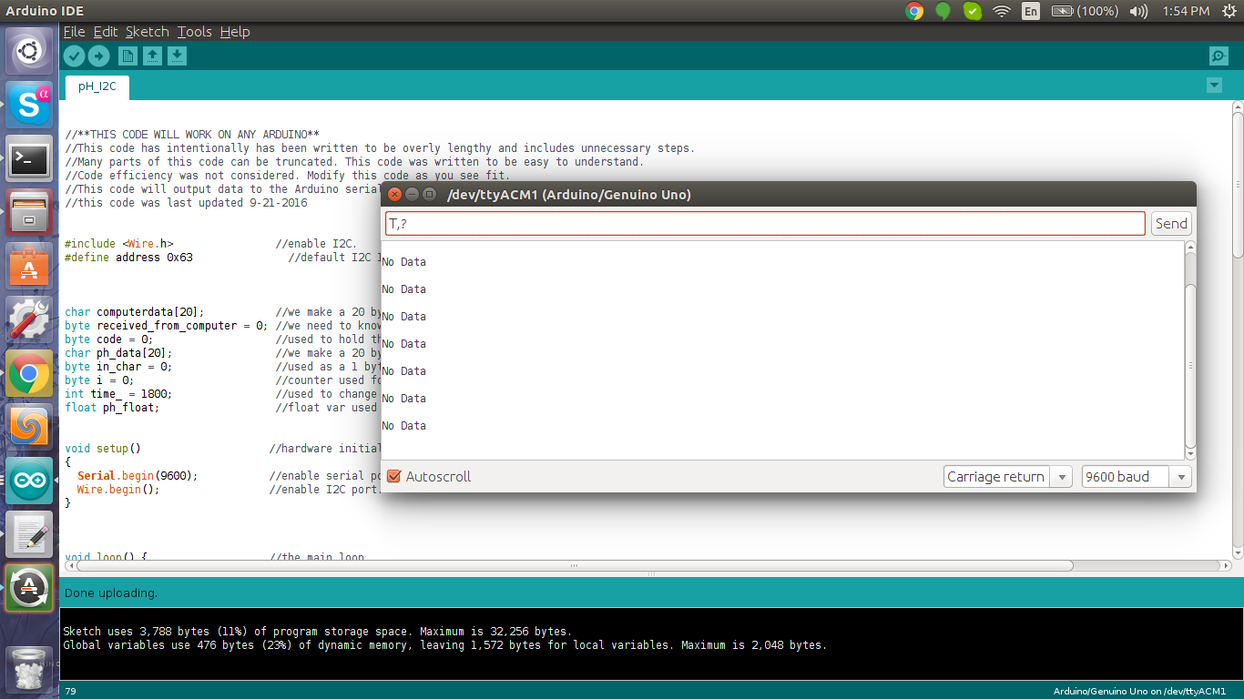
But I2C commands not responding always showing NO data.
Please find the attached screen shot.
Do we need to configure I2C clock anywhere?
How to get the device address of the I2C port? We are using I2C -6 port , but not detecting in my Ubuntu Linux machine.