Hi everyone,
I’m struggling to get OTA work with an Arduino R4 Wifi board, which is enabled with Blynk NCP. To start, I followed Blink NCP documentation to flash the board with Platform IO.
The device was then successfully added with the Blynk mobile app and by Wifi pairing with BLE.
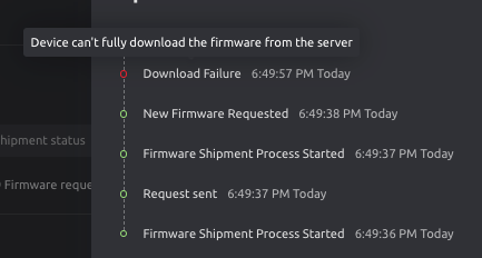
Now, when I try to ship a new firmware, I got an error message which says “Download Failure” and in details “device can’t fully download the firmware from server” :

What could I miss here ? OTA should be supported with this board, but maybe something is missing with my code to get it work ? For example, do I need to setup httpclient and url somewhere ? Also I’m not sure if OTA package tagging is mandatory in my case.
Thank you.
// Blynk Definition
#define BLYNK_TEMPLATE_ID "*******"
#define BLYNK_TEMPLATE_NAME "Premium Tank"
#define BLYNK_FIRMWARE_VERSION "0.1.3"
#define BLYNK_PRINT Serial

// URM14 Definition
#define   SLAVE_ADDR                ((uint16_t)0x0C)
#define   TEMP_CPT_SEL_BIT          ((uint16_t)0x01)
#define   TEMP_CPT_ENABLE_BIT       ((uint16_t)0x01 << 1)
#define   MEASURE_MODE_BIT          ((uint16_t)0x01 << 2)
#define   MEASURE_TRIG_BIT          ((uint16_t)0x01 << 3)

// ModbusMaster Definition
#define MAX485_DE      3
#define MAX485_RE_NEG  2

#include <BlynkEdgentNCP.h>
#include <ModbusMaster.h>

// instantiate ModbusMaster object
ModbusMaster node;

//URM14 Index Registers
typedef enum{
  ePid,
  eVid,
  eAddr,
  eComBaudrate,
  eComParityStop,
  eDistance,
  eInternalTempreture,
  eExternalTempreture,
  eControl,
  eNoise
}eRegIndex_t;//Sensor register index

//URM14 Function Read
/*
 *@brief Read data from holding register of client
 *
 *@param addr : Address of Client
 *@param reg: Reg index
 *@return data if execute successfully, false oxffff.
 */

uint16_t readData(eRegIndex_t reg)
{
  uint16_t data, result;
  result = node.readHoldingRegisters(reg, 1);
  if (!result == node.ku8MBSuccess){
    Serial.print("failed to read registers! ");
    data = 0xffff;
  }else{
    data = node.getResponseBuffer(0);
    Serial.print("data : ");
    Serial.print(data);
  }
  return data;
}

//URM14 Function Write
/*
 *@brief write data to holding register of client
 *
 *@param addr : Address of Client
 *@param reg: Reg index
 *@param data: The data to be written
 *@return 1 if execute successfully, false 0.
 */
uint16_t writeData(eRegIndex_t reg, uint16_t data)
{
  uint16_t result;
  result = node.writeSingleRegister(reg, data);
  if (!result == node.ku8MBSuccess){
    Serial.print("Failed to write coil! ");
    return 0;
  }else
    return 1;
}

//Variables Definition
float  dist;
volatile float tempInt;
volatile uint16_t cr = 0;
uint16_t tx = 0;
double nbLCuves = 0;
double txCuves = 0;
const int total_l = 5000;

//Blynk Functions
BlynkTimer timer;

BLYNK_CONNECTED() {
  BLYNK_LOG("Connected to Blynk 🙌");
  Blynk.syncVirtual(V1);
}

BLYNK_DISCONNECTED() {
  BLYNK_LOG("Blynk disconnected");
}

//ModbusMaster Functions
void preTransmission()
{
  digitalWrite(MAX485_RE_NEG, 1);
  digitalWrite(MAX485_DE, 1);
}

void postTransmission()
{
  delay(300);
  digitalWrite(MAX485_RE_NEG, 0);
  digitalWrite(MAX485_DE, 0);
}


//=====================Basic Setup ============================
void setup() {
  pinMode(MAX485_RE_NEG, OUTPUT);
  pinMode(MAX485_DE, OUTPUT);
  // Init in receive mode
  delay(300); //accord delay post init
  digitalWrite(MAX485_RE_NEG, 0);
  digitalWrite(MAX485_DE, 0);
  // Serials initialization
  Serial.begin(19200);
  Serial1.begin(19200);
  delay(3000);
  //*******************************************BLYNK SETUP
  BLYNKSetUp();
  timer.setInterval(1000L, myTimerEvent);
  node.begin(12, Serial1);
  // Callbacks allow us to configure the RS485 transceiver correctly
  node.preTransmission(preTransmission);
  node.postTransmission(postTransmission);

  cr |= MEASURE_MODE_BIT;//Set bit2 , Set to trigger mode
  cr &= ~(uint16_t)TEMP_CPT_SEL_BIT;//Select internal temperature compensation
  cr &= ~(uint16_t)TEMP_CPT_ENABLE_BIT;//enable temperature compensation
  writeData(eControl, cr); //Writes the setting value to the control register
  delay(100);
}

void BLYNKSetUp(void) {
  BLYNK_LOG("Main firmware: %s", BLYNK_FIRMWARE_VERSION);
  BLYNK_LOG("Build: %s", __DATE__ " " __TIME__);

  // Initialize the Blynk.NCP hardware
  if (Blynk.initNCP()) {
    String ver = Blynk.getNcpVersion();
    BLYNK_LOG("Blynk.NCP firmware: %s", ver.c_str());
  } else {
    BLYNK_LOG("Cannot communicate to Blynk.NCP");
    BLYNK_LOG("  Please ensure you have flashed your board with the Blynk.NCP firmware, before running this example.");
    BLYNK_LOG("  See: https://github.com/blynkkk/BlynkNcpExample");
    return;
  }

  // Print state changes
  Blynk.onStateChange([]() {
    BLYNK_LOG("State: %s", Blynk.getStateString());
  });

  // Set config mode timeout to 30 minutes, for testing purposes
  Blynk.setConfigTimeout(30*60);

  Serial.println("Blynk Connecting");
  Blynk.begin(BLYNK_TEMPLATE_ID, BLYNK_TEMPLATE_NAME);
  Serial.println("Blynk Connected");
}

void myTimerEvent() {
  Serial.println("Creation des variables");
  cr |= MEASURE_TRIG_BIT;//Set trig bit
  writeData(eControl, cr); //Write the value to the control register and trigger a ranging
  delay(300);//Delay of 300ms(minimum delay should be greater than 30ms) is to wait for the completion of ranging
  dist = (float)readData(eDistance) / 10;//Read distance register, one LSB is 0.1mm
  tempInt = (float)readData(eInternalTempreture) / 10.0;//Read the temperature register, one LSB is 0.1℃
  Serial.print("distance = ");
  Serial.print(dist, 1);
  Serial.println("mm");
    delay(100);
    nbLCuves = ((1655 - dist) * total_l / 2300);
    if (nbLCuves <= 0) {
      nbLCuves = 0;
    }
    txCuves = ((nbLCuves / total_l) * 100);
    delay(100);
    //*******************************************BLYNK VIRTUAL WRITE
    Serial.println("Virtual Writing At Blynk");

    Blynk.virtualWrite(V2, nbLCuves);
    Serial.print("nbLCuves=");
    Serial.println(nbLCuves);
    Blynk.virtualWrite(V3, txCuves);
    Serial.print("txCuves=");
    Serial.println(txCuves);
    Blynk.virtualWrite(V4, dist);
    Serial.print("dist=");
    Serial.println(dist);
    Blynk.virtualWrite(V5, tempInt);
    Serial.print("tempInt=");
    Serial.println(tempInt);
  }

void loop() {
  Blynk.run();
  timer.run();  // Initiates BlynkTimer
  delay(1);
}