Arduino Mega 2560 with w5100 Multiple DS18B20

Don’t be making so many assumptions :wink: I am still learning to code and have to spend much of my time Googling, reading and staring at example code, trying to pieces each puzzle part together. And if I can do that in my current foggy headed health, then I am sure you can in time as well.

PS, I volunteer here… I have no job or income due health issues… so please relax and be thankful someone is helping this much.

I have cleaned up the syntax and cleared out the redundant parts of your code… it compiles fine now, but I do not have the sensors or the Ethernet shield to test, so you need to take it from here again :wink:

// OneWire DS18S20, DS18B20, DS1822 Temperature Example
//
// http://www.pjrc.com/teensy/td_libs_OneWire.html
//
// The DallasTemperature library can do all this work for you!
// http://milesburton.com/Dallas_Temperature_Control_Library

#define BLYNK_PRINT Serial // Enables Serial Monitor
#include <SPI.h>
#include <Ethernet.h>
#include <BlynkSimpleEthernet.h> // This part is for Ethernet stuff
#include <OneWire.h>
#define W5100_CS  10
#define SDCARD_CS 4
BlynkTimer timer;
OneWire  ds(47);  // on pin 7 (a 4.7K resistor is necessary) make sure you change this from the original pin 10 to an unused pin.
int adr;
float s1;
float s2;
float s3;
byte i;
byte present = 0;
byte type_s;
byte data[12];
byte addr[8];
float celsius, fahrenheit;
char auth[] = "**********************cc79"; // Put your Auth Token here. (see Step 3 above)


void setup()
{
  Serial.begin(9600); // See the connection status in Serial Monitor

  pinMode(SDCARD_CS, OUTPUT);
  digitalWrite(SDCARD_CS, HIGH); // Deselect the SD card

  Blynk.begin(auth);  // Here your Arduino connects to the Blynk Cloud.
  // You can also specify server:
  //Blynk.begin(auth, "blynk-cloud.com", 8442);
  //Blynk.begin(auth, IPAddress(192,168,1,100), 8442);

  // Setup a function to be called every second
  timer.setInterval(1000L, myTimerEvent);
}


void myTimerEvent() {
  if ( !ds.search(addr)) {
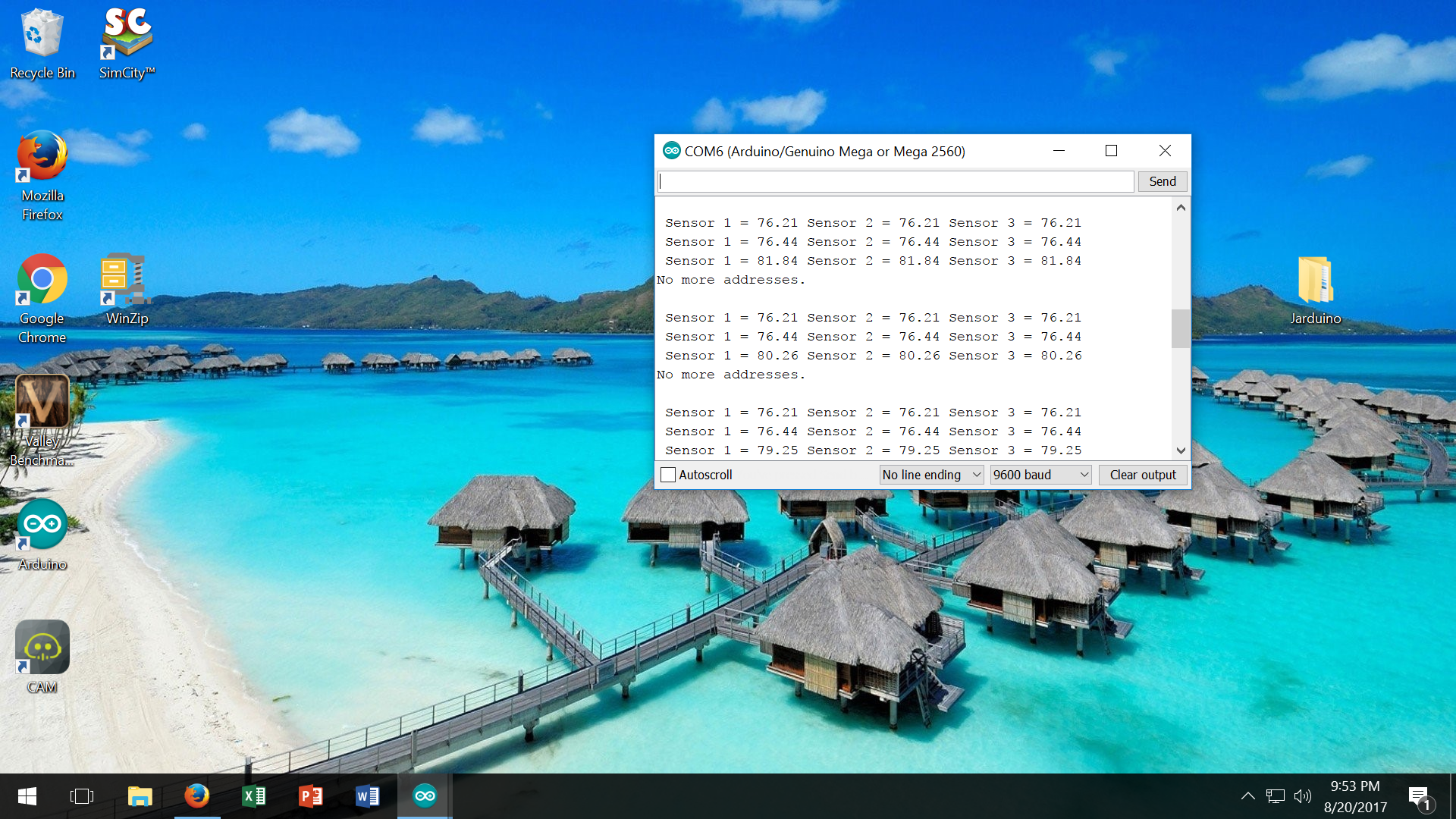
    Serial.println("No more addresses.");
    Serial.println();
    ds.reset_search();
    delay(250);
    return;
  }

  //  Serial.print("ROM =");
  for ( i = 0; i < 8; i++) {          //we need to drop 8 bytes of data
  }
  adr = (addr[7]);

  if (OneWire::crc8(addr, 7) != addr[7]) {
    Serial.println("CRC is not valid!");
    return;
  }

  ds.reset();
  ds.select(addr);
  ds.write(0x44, 1);        // start conversion, with parasite power on at the end

  // delay(1000);     // maybe 750ms is enough, maybe not
  // we might do a ds.depower() here, but the reset will take care of it.

  present = ds.reset();
  ds.select(addr);
  ds.write(0xBE);         // Read Scratchpad

  for ( i = 0; i < 9; i++) {           // we need 9 bytes to drop off
    data[i] = ds.read();
  }

  // Convert the data to actual temperature
  // because the result is a 16 bit signed integer, it should
  // be stored to an "int16_t" type, which is always 16 bits
  // even when compiled on a 32 bit processor.
  int16_t raw = (data[1] << 8) | data[0];
  if (type_s) {
    raw = raw << 3; // 9 bit resolution default
    if (data[7] == 0x10) {
      // "count remain" gives full 12 bit resolution
      raw = (raw & 0xFFF0) + 12 - data[6];
    }
  } else {
    byte cfg = (data[4] & 0x60);
    // at lower res, the low bits are undefined, so let's zero them
    if (cfg == 0x00) raw = raw & ~7;  // 9 bit resolution, 93.75 ms
    else if (cfg == 0x20) raw = raw & ~3; // 10 bit res, 187.5 ms
    else if (cfg == 0x40) raw = raw & ~1; // 11 bit res, 375 ms
    //// default is 12 bit resolution, 750 ms conversion time
  }
  celsius = (float)raw / 16.0;
  fahrenheit = celsius * 1.8 + 32.0;
  if (adr == 0x28, 0xAC, 0x35, 0xB9, 0x08, 0x00, 0x00, 0x4E )  {        //replace ??? with value of sensor number 1
    s1 = fahrenheit;           //change celsius to fahrenheit if you prefer output in Fahrenheit
  }

  if (adr == 0x28, 0xE6, 0x15, 0xBD, 0x08, 0x00, 0x00, 0x02 )  {        //replace ??? with value of sensor number 2
    s2 = fahrenheit;           //change celsius to fahrenheit if you prefer output in Fahrenheit
  }

  if (adr == 0x28, 0xA3, 0x49, 0xBC, 0x08, 0x00, 0x00, 0xA7 )  {        //replace ??? with value of sensor number 3
    s3 = fahrenheit;           //change celsius to fahrenheit if you prefer output in Fahrenheit
  }

  Serial.print(" Sensor 1 = ");
  Serial.print(s1);
  Serial.print(" Sensor 2 = ");
  Serial.print(s2);
  Serial.print(" Sensor 3 = ");
  Serial.println(s3);

  Blynk.virtualWrite(V5, s1);
  Blynk.virtualWrite(V6, s2);
  Blynk.virtualWrite(V7, s3); //add or delete if you need more or less
}


void loop()
{
  Blynk.run(); // All the Blynk Magic happens here...
  timer.run(); // Initiates BlynkTimer
}

Edited the sketch to make the last Serial.print() a Serial.println().

@Brett_Barnett I notice your very first screenshot was connecting you to cloud.blynk.cc and that server was retired 18 months ago. Connections should now appear as blynk-cloud.com.

1 Like

Thank you for fixing the code for me… I uploaded the sketch, and on the serial device I am seeing it read 3 lines of sensors… Before it goes to No More Addresses. I can heat up one of the sensors, as you can see the third line is reading more than the others. It would seem the way this is reading is each line is each different sensor rather than how it should be with each sensor reading differently. If that makes sense. I’m assuming its my code that is at fault. On the app, I have 3 different widgets. One reading V5, one reading V6, and one reading V7. All the temps on the gauge widgets are moving in unison like they are all reading off of one sensor. Any ideas? I would say that each line needs to be shortened from 3 sensors to just one, and then line 1 is sensor 1, and line 2, is sensor 2, etc.

Sorry, I have never worked with any one-wire sensors, so I am completely unfamiliar with the library and coding methods for these temp sensors. I am a hands on, visual learner and tend to need the hardware in front of me whilst I poke and prod at the code, watching the results, in order to get a better insight of how it works… so you might have to await someone else with more DS18B20 temperature probe experience.

Double check how the working non-blink code is and compare it with what is in your void myTimerEvent() function. maybe something got lost in the translation?

Also double check your setup and pre-setup incase you are not properly isolating each sensor as an independent… perhaps even strip it down to one sensor, get it working, then add then next, etc… Idunno :confused:

It has to be something wrong in the code… I can get it to read fine on the serial port with one of the earlier sketches at the top of this feed, but when I try to start messing with the Blynk code, it goes haywire on me. I think I may have even posted a picture of the serial port reading each sensor individually. We are close… It has to be something stupid. Lol

That’s ok… I am still learning about these sensors too… I think it’s cool how you can read a bunch of different sensors off of one wire… You suggested Google earlier… I’ve scoured Google for this same scenario, and have only found a couple, but the code didn’t work. There are some with different hardware too, I’ve been banging my head against the wall trying to figure this out… This is easy stuff compared to what I want the app to do in the long run… :slightly_frowning_face:

Hmm… As I look at it again, there seems to be much more in the setup of your initial code, then there is in the one I cleaned up for you…

I think you are missing some necessary code in the Blynkified sketch.

You better double check and add whatever is needed.

@Brett_Barnett you had a fairly standard DS18B20 sketch and then wandered off to a more obscure one.
The following compiles but I haven’t hooked up my sensors. You should see it is your working sketch plus a handful of lines to Blynkify it.

/*
  DS18B20multiple.ino https://community.blynk.cc/t/arduino-mega-2650-with-w5100-multiple-ds18b20/16706/10
  YourDuino Multiple DS18B20 Temperature Sensors on 1 wire
  Connections:
  DS18B20 Pinout (Left to Right, pins down, flat side toward you)
  - Left   = Ground
  - Center = Signal (Pin 2):  (with 3.3K to 4.7K resistor to +5 or 3.3 )
  - Right  = +5 or +3.3 V

   Questions: terry@yourduino.com 
   V1.01  01/17/2013 ...based on examples from Rik Kretzinger
   
/*-----( Import needed libraries )-----*/

#define BLYNK_PRINT Serial // Enables Serial Monitor
#include <SPI.h>
#include <Ethernet.h>
#include <BlynkSimpleEthernet.h> // This part is for Ethernet stuff

#define W5100_CS  10
#define SDCARD_CS 4
BlynkTimer timer;
char auth[] = "**********************cc79"; // Put your Auth Token here.
int Vpin = 5;  // will use Virtual pins 5, 6 and 7 for Sensor data

#include <OneWire.h> // Get 1-wire Library here: http://www.pjrc.com/teensy/td_libs_OneWire.html

//Get DallasTemperature Library here:  http://milesburton.com/Main_Page?title=Dallas_Temperature_Control_Library
#include <DallasTemperature.h>

/*-----( Declare Constants and Pin Numbers )-----*/
#define ONE_WIRE_BUS_PIN 47
/*-----( Declare objects )-----*/
// Setup a oneWire instance to communicate with any OneWire devices
OneWire oneWire(ONE_WIRE_BUS_PIN);

// Pass our oneWire reference to Dallas Temperature.
DallasTemperature sensors(&oneWire);

/*-----( Declare Variables )-----*/
// Assign the addresses of your 1-Wire temp sensors.
// See the tutorial on how to obtain these addresses:
// http://www.hacktronics.com/Tutorials/arduino-1-wire-address-finder.html

DeviceAddress Probe01 = { 0x28, 0xAC, 0x35, 0xB9, 0x08, 0x00, 0x00, 0x4E  }; 
DeviceAddress Probe02 = { 0x28, 0xE6, 0x15, 0xBD, 0x08, 0x00, 0x00, 0x02  };
DeviceAddress Probe03 = { 0x28, 0xA3, 0x49, 0xBC, 0x08, 0x00, 0x00, 0xA7  };

void setup()   /****** SETUP: RUNS ONCE ******/
{
  Serial.begin(9600);  // start serial port to show results
  Serial.print("Initializing Temperature Control Library Version ");
  Serial.println(DALLASTEMPLIBVERSION);
  
  sensors.begin(); // Initialize the Temperature measurement library
  
  // set the resolution to 10 bit (Can be 9 to 12 bits .. lower is faster)
  sensors.setResolution(Probe01, 10);
  sensors.setResolution(Probe02, 10);
  sensors.setResolution(Probe03, 10);

  pinMode(SDCARD_CS, OUTPUT);
  digitalWrite(SDCARD_CS, HIGH); // Deselect the SD card
  Blynk.begin(auth);  // Here your Arduino connects to the Blynk Cloud.  
  timer.setInterval(1000L, myTimerEvent);  // Setup a function to be called every second
}//--(end setup )---

void loop()   /****** LOOP: RUNS CONSTANTLY ******/
{
  Blynk.run(); // All the Blynk Magic happens here...
  timer.run(); // Initiates BlynkTimer   
}//--(end main loop )---

void myTimerEvent() {
  Serial.print("Number of Devices found on bus = ");  
  Serial.println(sensors.getDeviceCount());   
  Serial.print("Getting temperatures... ");  
  Serial.println();   
   
  sensors.requestTemperatures();  // Command all devices on bus to read temperature  
  
  Serial.print("Probe 01 temperature is:   ");
  printTemperature(Probe01); 
  Serial.println();

  Serial.print("Probe 02 temperature is:   ");
  printTemperature(Probe02);
  Serial.println();
 
  Serial.print("Probe 03 temperature is:   ");
  printTemperature(Probe03);
  Serial.println();  
}

/*-----( Declare User-written Functions )-----*/
void printTemperature(DeviceAddress deviceAddress)
{
   
   float tempC = sensors.getTempC(deviceAddress);

   if (tempC == -127.00) 
   {
    Serial.print("Error getting temperature  ");
   } 
    else
   {
     Serial.print("C: ");
     Serial.print(tempC);
     Serial.print(" F: ");
     Serial.print(DallasTemperature::toFahrenheit(tempC));
     Blynk.virtualWrite(Vpin, DallasTemperature::toFahrenheit(tempC));
     Vpin++;
     if(Vpin >= 8){   // cycle through pins V5 to V7
        Vpin = 5;
     }
   }
}// End printTemperature
//*********( THE END )***********
1 Like

You are the man!! Thank you a ton!!! Works great and all sensors read like they are supposed to. I was trying to play around with switching the one wire bus pin to pin D51, but for some reason I can’t my sensors to read anything on that pin… Is there a reason for this, or is there a way to make pin 51 work?? Or am I stuck using pin 47? When I switch the sketch to #define ONE_WIRE_BUS_PIN 51 the serial port doesn’t see any devices on this pin… I am also having an issue with pin 52… I have it on a button widget to turn a relay on and off… When the arduino connects online, the relay connected to pin 52 stays on and I can’t turn it off or on with the button widget… Pin 53 works good with a relay, but I need both 52 and 53 to work.

On the Mega, pins 50-53 are also part of the SPI interface, so perhaps some conflicts with the One-Wire library?

Thankfully on the Mega, you have many pins to chose from.

I know there are a ton of pins… I tried to switch to 14,15 51,… None gave me any readings… I have to watch what pins I’m using for what… Trying to keep everything as close to this pinout as I can. This is what I’m trying to get set up eventually…

Hmmm… I have never used it so am unsure, but based on some reading here, One Wire looks to require an Analog pin for hookup, not a Digital pin.

http://playground.arduino.cc/Learning/OneWire

EDIT: Ok, it seems it should work on Digital pins as well… so no real solution there :wink:

https://www.hacktronics.com/Tutorials/arduino-1-wire-tutorial.html

Why do you need to follow a set pin out, can’t you pick any available pin (that works of course)?

I can to a point… I would have to change the huge sketch that I have for my aquarium controller… This is why I was trying different pins… I could use digital pins 14-19 but I tried to change the sketch that @Costas made to reflect this, but the sensors wouldn’t read. Do I need to change something other than the one wire bus number in the sketch?

@Brett_Barnett my understanding is that you can use any digital pin on the Mega for DS18B20 sensors.

Are you sure it was wired up correctly when you moved it from pin 47?

I agree with @Costas… are you also moving the 4.7k Ohm pull up resistor, as seems to be required for these sensors?

Absolutely… There is only one wire (hence one wire sensor) to move. The other two wires are 5volt and ground. I tried changing the code that assigns the pin bus from 47 to pin 51,also tried digital pin 14, 15… When I changed the code I also moved the one data wire to the same pin as in the code, and it doesn’t pick up the sensors in the serial monitor … For some reason it only works on pin 47… I thought this to be strange… The 4.7kohm resistor is on a bread board with my sensors, so that is not the issue. The serial monitor finds 0 devices and prints out probe 1, 2, and 3 Temps as 0C and 32F. Hopefully this helps.

OK, just in case something else is slipping through…

Can you show us your full code, with the sensor pin on your next best choice (NOT 47).

As well as show us the serial monitor output.

Thanks

/*
  DS18B20multiple.ino https://community.blynk.cc/t/arduino-mega-2650-with-w5100-multiple-ds18b20/16706/10
  YourDuino Multiple DS18B20 Temperature Sensors on 1 wire
  Connections:
  DS18B20 Pinout (Left to Right, pins down, flat side toward you)
  - Left   = Ground
  - Center = Signal (Pin 2):  (with 3.3K to 4.7K resistor to +5 or 3.3 )
  - Right  = +5 or +3.3 V

   Questions: terry@yourduino.com 
   V1.01  01/17/2013 ...based on examples from Rik Kretzinger
   
/*-----( Import needed libraries )-----*/

#define BLYNK_PRINT Serial // Enables Serial Monitor
#include <SPI.h>
#include <Ethernet.h>
#include <BlynkSimpleEthernet.h> // This part is for Ethernet stuff

#define W5100_CS  10
#define SDCARD_CS 4
BlynkTimer timer;
char auth[] = "******************ecc79"; // Put your Auth Token here.
int Vpin = 5;  // will use Virtual pins 5, 6 and 7 for Sensor data

#include <OneWire.h> // Get 1-wire Library here: http://www.pjrc.com/teensy/td_libs_OneWire.html

//Get DallasTemperature Library here:  http://milesburton.com/Main_Page?title=Dallas_Temperature_Control_Library
#include <DallasTemperature.h>

/*-----( Declare Constants and Pin Numbers )-----*/
#define ONE_WIRE_BUS_PIN 51
/*-----( Declare objects )-----*/
// Setup a oneWire instance to communicate with any OneWire devices
OneWire oneWire(ONE_WIRE_BUS_PIN);

// Pass our oneWire reference to Dallas Temperature.
DallasTemperature sensors(&oneWire);

/*-----( Declare Variables )-----*/
// Assign the addresses of your 1-Wire temp sensors.
// See the tutorial on how to obtain these addresses:
// http://www.hacktronics.com/Tutorials/arduino-1-wire-address-finder.html

DeviceAddress Probe01 = { 0x28, 0xB8, 0x67, 0x26, 0x00, 0x00, 0x80, 0x0D  }; 
DeviceAddress Probe02 = { 0x28, 0xFF, 0x6E, 0x21, 0xA0, 0x16, 0x03, 0x56  };
DeviceAddress Probe03 = { 0x28, 0xFF, 0xA7, 0x0A, 0xA0, 0x16, 0x04, 0xE0  };

void setup()   /****** SETUP: RUNS ONCE ******/
{
  Serial.begin(9600);  // start serial port to show results
  Serial.print("Initializing Temperature Control Library Version ");
  Serial.println(DALLASTEMPLIBVERSION);
  
  sensors.begin(); // Initialize the Temperature measurement library
  
  // set the resolution to 10 bit (Can be 9 to 12 bits .. lower is faster)
  sensors.setResolution(Probe01, 12);
  sensors.setResolution(Probe02, 12);
  sensors.setResolution(Probe03, 12);

  pinMode(SDCARD_CS, OUTPUT);
  digitalWrite(SDCARD_CS, HIGH); // Deselect the SD card
  Blynk.begin(auth);  // Here your Arduino connects to the Blynk Cloud.  
  timer.setInterval(1000L, myTimerEvent);  // Setup a function to be called every second
}//--(end setup )---

void loop()   /****** LOOP: RUNS CONSTANTLY ******/
{
  Blynk.run(); // All the Blynk Magic happens here...
  timer.run(); // Initiates BlynkTimer   
}//--(end main loop )---

void myTimerEvent() {
  Serial.print("Number of Devices found on bus = ");  
  Serial.println(sensors.getDeviceCount());   
  Serial.print("Getting temperatures... ");  
  Serial.println();   
   
  sensors.requestTemperatures();  // Command all devices on bus to read temperature  
  
  Serial.print("Probe 01 temperature is:   ");
  printTemperature(Probe01); 
  Serial.println();

  Serial.print("Probe 02 temperature is:   ");
  printTemperature(Probe02);
  Serial.println();
 
  Serial.print("Probe 03 temperature is:   ");
  printTemperature(Probe03);
  Serial.println();  
}

/*-----( Declare User-written Functions )-----*/
void printTemperature(DeviceAddress deviceAddress)
{
   
   float tempC = sensors.getTempC(deviceAddress);

   if (tempC == -127.00) 
   {
    Serial.print("Error getting temperature  ");
   } 
    else
   {
     Serial.print("C: ");
     Serial.print(tempC);
     Serial.print(" F: ");
     Serial.print(DallasTemperature::toFahrenheit(tempC));
     Blynk.virtualWrite(Vpin, DallasTemperature::toFahrenheit(tempC));
     Vpin++;
     if(Vpin >= 8){   // cycle through pins V5 to V7
        Vpin = 5;
     }
   }
}// End printTemperature
//*********( THE END )***********

Could you also please tell me how to get my code into it’s own box with a right side slider so it doesn’t make this feed a mile long? LOL

Also, please copy/paste serial monitor info instead of screenshots… some of us are near blind :sunglasses:

1 Like