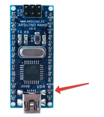
@esa your Nano is 5V as the Pro Mini is the only Arduino with 3.3V, right?
Doesn’t the Nano burn out the 3.3V rx line?
Do I need to flash esp with blank sketch or something else?
3.3v I take with nano. rx, tx are connected on a straight line. No what has burned down.-))

I have an empty, ie, the entire program is only for arduino nano.
But there is a second option. You flood the program arduino (with sensor data collection) and embedded software for the esp (exchange with blynk)? as well as in two programs (arduino and esp) writing transmit and receive data on the serial.
@legionercheg what @esa describes in the last post is our connection method 3. (ESP with Arduino shield).
I have connected on a straight line. For esp has bought here what
@esa, thanks a lot about your explanation! Today I’m going to try “your” method)) May I send you private messages if something goes wrong?)
@legionercheg please take a look at this “live” thread which confirms it’s not normally a 2 step process for most “shield” users [SOLVED] Arduino + ESP8266 ESP-01(AI-Cloud, Black Version)
Obviously we are all here to help whichever method of connection you decide to choose.
Many Blynkers start with one method and then try others before settling on what is best for them.
I was initially a shield user and with around 60 Arduino’s in the house you can understand why, like you, I chose this route.
I have a bit of a phobia with soldering irons and breadboards are not always 100% effective so the Blynk plug and play system, ESP’s with USB ports, became my preferred connection method.
Blynk have said themselves they are not Arduino fans as far as connecting to Blynk is concerned. They were not designed for internet use whereas other hardware was. So development time is likely to concentrate on connection methods that are reliable and popular.
As indicated by @esa there are some shield users that have found the shield connection process straightforward and we hope you and others do too.
Please keep us updated with your progress as it’s sure to help others, whether that is to make it easier for them to use shields with Blynk or help them decide on an alternative connection method.
Connected arduino Uno and esp via Software Serial, flashed esp with blank sketch and Uno with blynk standart example ESP8266 wifi shield, but after flashing Uno got an error in Serial port-“Failed to disable echo”. In others topics here found that it might be because of firmware of esp that is not updated to last version (0.22 AT). But then I got stuck-downloaded ESP Download Tool 3.4.4, flashed my ESP with the recomendations from readme file:
Opened PUTTY and trying to connect to ESP-no answer!
Found single *bin file to flash via esp8266_flasher, but the version was 0.21 AT.
I don’t understand anything now:sob:
I can’t flash my ESP-12f  Is there any working instruction? Maybe not the instruction but the working link for firmware! The links to esp8266.ru for 0.22 AT firmware are broken
I stitched the utility of XTCOM_UTIL. The instruction is, only it in Russian.The only minus of this utility, it works only com1-com6
@legionercheg I think you now have the dreaded “Failed to disable echo” issue.
This is normally associated with incorrect baud rates.
@esa’s 2 point guideline for “shields”, 7 points by Blynk and 10 points if I bother to make a guideline, only works if you go straight for Arduino with ESP as shield. Many users try the ESP standalone method first and this removes the AT firmware. It is then much more involved.
Look through this thread [SOLVED] Arduino + ESP8266 ESP-01(AI-Cloud, Black Version) including the useful 7 point guide by @dwadia
So,finally what I wanted to say-I tried (like I think) every possible variants of connections.
1)With esp12f witty cloud-rx and tx of esp were connected to 2,3 digital ports at arduino,or then directly to tx and rx on arduino. Then I made a resistor devider thinking that esp don’t understand the 5v logic,so resistors should transform 5v from arduino’s tx pin to 3,3v. But this didn’t work either.
2)After that I take esp-01,flashed it with firmware that @esa posted here,connected to arduino UNO like was with esp-12f but after all that the result was the same:
[19]
___ __ __
/ _ )/ /_ _____ / /__
/ _ / / // / _ / '/
///_, /////_
/__/ v0.4.3 on Arduino Uno
[603] Connecting to dlink_inet
[1619] Failed to disable Echo
I’m tired of this and now will be using esp-12f witty cloud only for receiving digital signals from arduino(if some values goes HIGH arduino will turn HIGH some pins and esp sees that translate this to blynk to LED widget) or in standalone mode! And ordering an ADS1115 analog extension board for esp.


I don’t understand why doesn’t work for you.
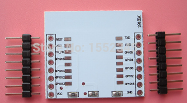
I connected esp-12 to arduino as follows (I esp soldered on shield, Photo see a few posts above).
arduino ------ esp-12
3.3 ------ vcc, ch_pd
gnd ------ gnd, gpio15
rx ------ pin 2
tx ------ pin 3
gnd ------ gpio0 (programming (flashing) mode)
Next download program to arduino
#include <SoftwareSerial.h>
SoftwareSerial mySerial(3, 2);

void setup()
{
  Serial.begin(9600);
  while (!Serial) {
    ;
  }

  mySerial.begin(9600);
}

void loop()
{
  if (mySerial.available())
    Serial.write(mySerial.read());
  if (Serial.available())
    mySerial.write(Serial.read());
}
Next to the monitor port (arduino ide) enter the AT commands. If done correctly, you should see a response from esp. In the example, change the speed of esp, if you do it the other
Here is a diagram how to connect esp-12, if you do not use a shield
I’m on this article makes a connection, but it’s in Russian
I’m sorry for my English, because it is not my mother tongue
@esa, I’ve got esp-12f witty cloud,which look like that:
http://des.volumebest.com/uploads/pdm-desc-pic/Electronic/image/2016/01/28/1453943027103981.jpg
So the connection is more simple than with esp-01,07 or 12. I just need to power it (pins Vcc and Gnd) and connect RX and TX pins. Flashing it is going in automatic mode. So it looks like everything is very simple,but no one of many advices worked for me ![]() I spent 3 or 4 days for trying and googling about this problem. Now I don’t know what else to do.
I spent 3 or 4 days for trying and googling about this problem. Now I don’t know what else to do.
Не переживай, english тоже не мой родной язык ![]()
![]()
Try this forum. It can help there.
http://arduino.ru/forum/obshchii/upravlyaem-arduinoi-cherez-internet
