Above is my circuit diagram to connect with NodeMCU ESP8266.
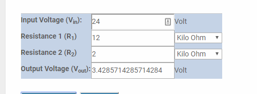
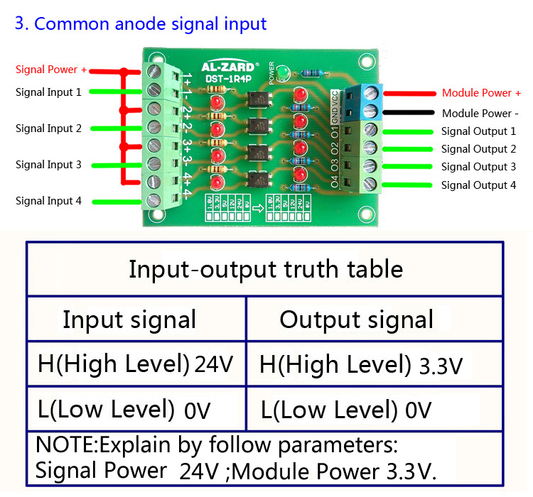
What I am doing is, various independent 24V signals will be converted into 3.3V zenor diode, then connect into different DI/O on the board.
For, D0, if status is HIGH, then value0 = bit(0), else 0
For, D1, if status is HIGH, then value1 = bit(1), else 0
…etc until D10
The program will combine all value automatically by a time interval (1),
VALUE = value 0 |= value 1 … |= value 10
and Email will be sent out with VALUE as content by a time interval (2).
The program has tested and success do what I want, However, the hardware problem occurs.
I used the BUTTON at Blynk, the board can sense the status of its pin HIGH or LOW
I used the 3.3v supply from the board and connect to different DI/O, the board can still sense the pins HIGH or LOW
BUT, when I used above circuit to connect my designed 3.3V signal, the board cannot sense,
(i.e. values are always zero)
My questions are:
- Why both the supply are 3.3V (from MCU board / my designed circuit), but the board only recognize the previous one, it just sample, just put a 3.3v signal into a pin.
- When the Resistor (Ra/Rb/Rc) is used 330 ohms, the resistor starts to burn and have burnt smell, but Vout measured on the board fulfill 3.3V, but if I used 1K ohms, the resistor will not burn and no smell, but Vout only supply 1.x V (sorry my meter cannot read decimal places)
So, How to calculate the correct value for the resistors?
Thank you