Hi guys. I want to read ZMPT101 module analog data with blynk but when using blynk the speed of reading data is very slow. can someone help me how to buffer the analog data then send it to virtualpin ?
thanks for any help.
Hi guys. I want to read ZMPT101 module analog data with blynk but when using blynk the speed of reading data is very slow. can someone help me how to buffer the analog data then send it to virtualpin ?
thanks for any help.
Blynk Legacy or IoT?
Type of Dev Board?
Connectivity method?
Code?
Pete.
thanks for reply.
blynk legacy with local server.
Nodemcu.
WiFi connection.
for the code I just need an example how to buffer analog data, then send the buffered data to the virtualpin.
What code are you using, to give the very slow results?
Pete.
int analogPin = A0;

int val = 0;

void adcread() {
  val = analogRead(analogPin);
  Blynk.virtualwrite(V1, val);
  Serial.println(val);
}
This feels like pulling teeth!
How often are you calling this function?
Are you calling it with a Blynk Timer?
How slow is this process, and how fast would you like it to be?
Pete.
yes I used blynk timer with 10ms delay. but it’s not enough for reading the AC sine wave
Are you trying to measure voltage or current?
Have you calibrated the ZMPT101 using the onboard potentiometer and the serial plotter?
Pete.
Somewhat confusing. If you are reading a 60 Hz waveform, 10 msec is way to slow if you want to see the actual waveform (16 msec per full cycle.) I have used that module with the Arduino graphing option as Pete suggests and the A/D is plenty fast enough to resolve the waveform. However, that can’t be what you want the virtual pin to display. If you want to measure voltage you need to build a function that loops and continually evaluates the A/D output while looking for a maximum and minimum and then return that value and write it to the virtual pin. Loop count needs to be long enough and fast enough so that you make sure to get a maximum and then drop out and display the result in Blynk.
You can get all this from Open energy Monitor at Learn | OpenEnergyMonitor
@PeteKnight @ScottB Thanks for reply.
Here is my full project:
Voltage and current are not considered in this project.
I want to measure the phase sequence ( phase angle ) between two points.
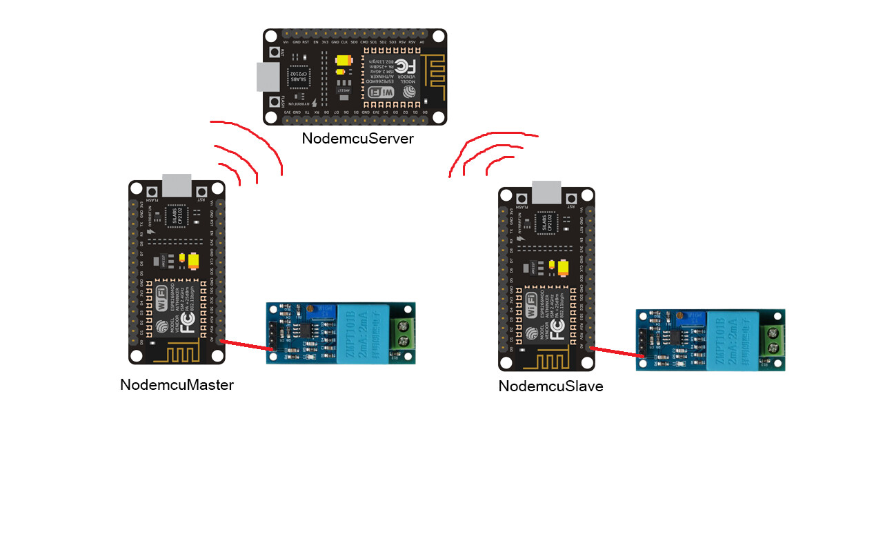
three nodemcu’s used in this project:
NodemcuServer, NodemcuMaster and NodemcuSlave
NodemcuMaster: reading the ZMPT101B sine wave from A0 pin and send data to NodemcuServer with bridge ( on virtual pin 1 ).
NodemcuSlave: reading the ZMPT101B sine wave from A0 pin and send data to NodemcuServer with bridge ( on virtual pin 2 ).
NodemcuServer: receiving data (sine wave ) from NodemcuMaster and NodemcuSlave then processing and calculating the phase angle between two points.
the arduino codes:
NodemcuMaster:
#include <ESP8266WiFi.h>
#include <BlynkSimpleEsp8266.h>

WidgetBridge bridge1(V0);

BLYNK_CONNECTED()
{
  bridge1.setAuthToken("BFS7mu74eDPoO2jGg2QUkq4wQenGKIZk");
}

char auth[] = "WfUINi1oRBeTS8Tez-JHn45Leac8tzFY";
char ssid[] = "MikroTik Tesla";
char pass[] = "12345678";
char server[] = "10.5.51.5";

void setup()
{
  Serial.begin(9600);
  Blynk.begin(auth, ssid, pass, server, 8080);
}

void loop()
{
  while (!Blynk.connected()) {
    Blynk.connect();
  }
  Blynk.run();
  int x = analogRead(A0);
  Serial.println(x);
  bridge1.virtualWrite(V1, x);
}
NodemcuSlave:
#include <ESP8266WiFi.h>
#include <BlynkSimpleEsp8266.h>

WidgetBridge bridge1(V0);

BLYNK_CONNECTED()
{
  bridge1.setAuthToken("BFS7mu74eDPoO2jGg2QUkq4wQenGKIZk");
}

char auth[] = "3_k_-x-ib_UKeNeHWvJpypqlNMIr5Rex";
char ssid[] = "MikroTik Tesla";
char pass[] = "12345678";
char server[] = "10.5.51.5";

void setup()
{
  Serial.begin(9600);
  Blynk.begin(auth, ssid, pass, server, 8080);
}

void loop()
{
  while (!Blynk.connected()) {
    Blynk.connect();
  }
  Blynk.run();
  int x = analogRead(A0);
  Serial.println(x);
  bridge1.virtualWrite(V2, x);
}
NodemcuServer:
#include <ESP8266WiFi.h>
#include <BlynkSimpleEsp8266.h>

BlynkTimer timer;

WidgetBridge bridge1(V0);

int master = 0;
int slave = 0;
int decimalPrecision = 2;                           // decimal places for all values shown in LED Display & Serial Monitor
int expectedFrequency = 50;                         // Key in frequency for main grid (50 / 60 hz)                         // The input pin for analogRead1 sensor. Use voltage sensor as primary reference here.
float voltage1AnalogOffset = 0;                     // This is to offset analog value for analogInput1
float voltage2AnalogOffset = 0;                     // This is to offset analog value for analogInput2
unsigned long startMicrosVPRM;                      /* start counting time for Phase Angle and Period (in micro seconds)*/
unsigned long CurrentMicrosVPRM1;                   /* current time for analogInput1 (voltage) (in micro seconds). AnalogInput1 is used for reference for phase angle*/
unsigned long CurrentMicrosVPRM2;                   /* current time for analogInput1 (voltage) (in micro seconds). AnalogInput1 is used for reference for phase angle*/
unsigned long CurrentMicrosPeriod;                  /* current time to measure period of wave */
float vAnalogValue1 = 0;                            /* is the analog value for voltage sensor / analogInput1 and center at 0 value */
float vAnalogValue2 = 0;                            /* is the analog value for current sensor / analogInput2 and center at 0 value */
float periodWave1;                                  /* total time taken for whole set */
float periodWave2;                                  /* total time taken for whole set */
float periodAverage;                                /* period of the first voltage wave */
float phaseAngle = 0;                               /* is the time difference between 2 sensor values (in micro seconds) */
float sampleCount = 0;                              /* count the number of sample*/
int switchOperation = 5;                            /* use for switching operation*/
int record2Switch = 1;                              /* use for switching operation*/
int record1Switch = 1;                              /* use for switching operation*/
float previousPhaseAngle = 0;                       /* previous value use to replace over limit value */

char auth[] = "BFS7mu74eDPoO2jGg2QUkq4wQenGKIZk";
char ssid[] = "MikroTik Tesla";
char pass[] = "12345678";
char server[] = "10.5.51.5";

void setup()
{
  Serial.begin(9600);
  Blynk.begin(auth, ssid, pass, server, 8080);
  timer.setInterval(10L, volt);
}

BLYNK_WRITE(V1)
{
  master = param.asInt();
}

BLYNK_WRITE(V2)
{
  slave = param.asInt();
}

void volt()

void loop()
{
  Blynk.run();
  timer.run();
}I don’t see how that can work.
Surely you need some way of accurately synchronising the two devices that are taking the readings, and if you want t measure the phase angle shift to within 1 degree then that synchronisation needs to be within 50 microseconds.
Pete.
do you have any solution?
No. Using NTP doesn’t even give you that accuracy over public internet, so a physical connection is probably the only option, and that probably isn’t viable for your purposes.
Pete.