@jasperdog My suspicion is that your Arduino IDE is still using the old espalexa library. I’ve occasionally had issues with the Arduino compiler choosing the wrong one. If you’re still interested in using Alexa routines, try completely deleting the old espalexa library first. At this point, the code should fail to compile because of the missing library. Once you’ve confirmed that it’s gone, install the new espalexa library, restart the IDE, and upload to your device. BTW, thanks for pointing out the missing Blynk widget updates. I’m posting a new version today that fixes the issue.
CODE UPDATE:
- Fixed missing Blynk widget sync
- All device settings now in one location, including single variable to select between ON/OFF and PWM operation.
/* Wemo / Hue emulation for ESP8266 control with Alexa, Blynk and IFTTT.
 *
 * https://github.com/tzapu/WiFiManager
 * https://github.com/Aircoookie/Espalexa
 * https://www.blynk.cc/
 *
 * Can be configured for either ON/OFF control or analog (PWM). If using a Blynk slider,
 * assign a range of 0-255 to the widget.
 *
 * For IFTTT control, use the Maker Channel with the following settings:
 *    URL: http://blynk-cloud.com:8080/YOUR_TOKEN/V1       Substitute your own token and vitual pin
 *    Method: PUT
 *    Content type: application/json
 *    Body: {"1"]                                          Use 0 for OFF, 1 for ON. For custom levels use 0-255.
 */

#include <ESP8266WiFi.h>
#include <DNSServer.h>
#include <ESP8266WebServer.h>
#include <WiFiManager.h>
#include <Espalexa.h>
#include <ArduinoOTA.h>
#include <BlynkSimpleEsp8266.h>

//  Device customizations  //////////////////////////////////////////////////////////////////////////////////////////
#define VPIN V1                   //Use a unique virtual pin for each device sharing the same Blynk token / dashboard
char auth[] = "YOUR_TOKEN"    ;   //Get a token from Blynk
char DeviceName[] = "Switch One"; // How you want the switch to be named in the Alexa app
boolean UsingPWM = false;         // "False" if using a relay and Blynk button. "True" if using PWM and Blynk slider.
const int OutputPin = D1;         // Output pin to a relay or PWM device. The onboard relay on a Sonoff is pin 12.
/////////////////////////////////////////////////////////////////////////////////////////////////////////////////////

Espalexa espalexa;

void setup(){
  Serial.begin(115200);

  WiFiManager wifi;
  wifi.autoConnect("EspalexaSwitch"); // Connect to this access point the first time you use the device

  // Initialize the new device
  espalexa.addDevice(DeviceName, UpdateSwitch1); //Parameters: (device name, callback function)
  espalexa.begin();

  pinMode(OutputPin, OUTPUT);   // This can be used for either a relay or PWM output
  digitalWrite(OutputPin, LOW);

  Blynk.config(auth);

  ArduinoOTA.begin();
}

void loop()
{
   espalexa.loop();
   Blynk.run();
   ArduinoOTA.handle();
}

//------------ Callback functions. Level can be set from 0-255. -------------
void UpdateSwitch1(uint8_t level) {   // Espalexa callback
  SetNewLevel(&level);
}

// Handle blynk widget. Can be a switch or a slider
BLYNK_WRITE(VPIN){
  uint8_t level = param.asInt();
  SetNewLevel(&level);
}

void SetNewLevel(uint8_t * pLevel){
  Serial.print("New level= ");
  Serial.println(*pLevel);

  // If the new level is not 0, turn on the relay or set the output pin's PWM
  if (*pLevel) {
    if(UsingPWM){
      // Incoming level (0-255) multiplied by 4 to align with the ESP's PWM levels (0-1023)
      analogWrite(OutputPin, *pLevel * 4);
      Blynk.virtualWrite(VPIN, *pLevel);
    }
    else{
      digitalWrite(OutputPin, HIGH);
      Blynk.virtualWrite(VPIN, HIGH);
    }
  }
  // Turn off the output pin if the new level is 0
  else  {
    digitalWrite(OutputPin, LOW);
    Blynk.virtualWrite(VPIN, LOW);
  }
}
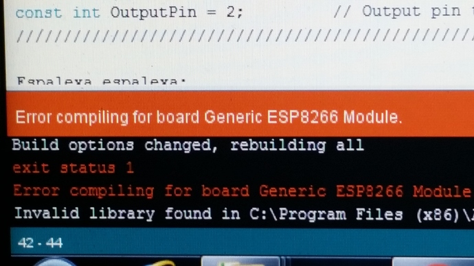
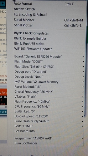
haaa @chrome1000 i just can’t resist another crack at this. Followed all your advice regarding libraries etc. updated arduino ide to 1.85 latest. compile fails everytime within 10 seconds of compiling with the message in photo 1. i’m testing on a esp-01 generic board using pin 2 as normal, tried changing board type and pin number but same error as photo 1, so i’m guessing it’s my ide esp8266 settings photo 2, can you check against your ide settings to see weather it’s in conflict, by the way because i was using pin 2 i changed the builtin led setting to ‘0’ but same error.
…UPDATE… it was the ESP8266 board version 2.4.2.
downgraded to 2.3.0 and now compiles, will test when flashed.
ok it all works and syncs together including the “light on issue” is resolved too.
only question is does the below line need changing to suit the new device name
espalexa.addDevice(DeviceName, UpdateSwitch1); //Parameters: (device name, callback function)
i.e if i call my second device “switch two” do i need to change that line to updateswitch2
well done @chrome1000, Everything is working including the elusive “Routines”. In conclusion the only anomaly is the ESP8266 2.4.2 board problem, i don’t know what is wrong with it to stop everything compiling, including my older sketches too. Which only proves it must be the update to 2.4.2.
The device name doesn’t need to have any relationship to the callback name. You can name either of them however you like.
That said, if you were to use a single ESP to emulate multiple devices (Switch One, Switch Two, Switch Three…), giving your callback functions names that relate their associated device names would make the code easier to follow and debug.
@chrome1000 many thanks for your help, all devices are up and running now, funnily enough the only issue i had was that OTA on Sonoff devices didn’t work, (all other devices like wemos d1 mini and my homemade esp-01 switches) worked OTA fine. i needed to unwire them (sonoffs) and hard flash via the laptop, now reflashed and OTA now works again, very strange…must be a bug in the esp8266 board version, by the way i’m still having to use version 2.3.0 due to the compiling errors using 2.4.2. i confirm everything in the Alexa app is working including the always on issue is now working correctly and so are Groups, routines and timers etc…really good project. I’ve ordered some wifi bulbs, so will incorporate these when i get them too.Hope all this helps other people that are experiencing the same issues.
Certain ESP8266 variants like the Sonoff and ESP-01 don’t have enough memory to make use of OTA.
You can do OTA on Sonoffs provided your code is small enough. The device needs enough memory to store the existing code and the new code, so with a 1MB device your code can’t be larger than 512K.
You may also need to edit your boards file in the IDE to ensure you’re not allocating any unnecessary memory to SPIFFS.
It’s also possible to replace the flash chips on the ESP8266 based Sonoffs if you have a steady hand…
It also makes a difference which flash mode you use when compiling your code. DOUT was always the mode to use, but I’ve had a few issues with one mode working via direct flash mode and another being needed for OTA. Do a few tests to make sure what works with your particular versions of everything and add some notes at the top of your code which reminds you which settings to use.
Pete.
I have had good results with Sonoff using OTA, Core 2.4.2 and DOUT flash mode…
yeah @Gunner i meant to follow up, my issue as i first thought to be 2.4.2 was infact in conclusion the sonoff memory was not enough for this particular OTA sketch considering the size of the already existing sketch that the sonoffs were running. I too can confirm 2.4.2 works fine OTA, I thought it was strange that i didn’t encounter the same OTA issue when updating a wemos d1 mini with the same update sketch as the sonoffs, of course they have 4MB.compared to the 1MB on the sonoff. The only anomaly being that the OTA worked on my homemade esp-01 switch which only has 512kb? Anybody hazzard a guess as to why it was only all 3 sonoffs that failed the OTA update, all 5 devices had the exact existing OTA sketch on them, i was updating all 5 devices with the same new espalexa sketch, the esp-01 and wemos d1 both OTA success whilst all 3 sonoffs failed (needed connecting to laptop and hard flashed)? Just for info, now all are running the new OTA Espalexa sketch, OTA updates are now possible on all 5 devices.
I uploaded this sketch to a NODEMCU ESP8266 D1 Mini and in the serial monitor I just get a few characters of garbage such “⸮$F⸮⸮rJ⸮” and nothing else happens. What am I doing wrong?
I have confirmed the ESP8266 is on my wifi network but I never got the FAKEWEMO SSID to configure it. It is also connected to Blynk but Alexa cannot find anything. I don’t understand why it is configured to my wifi. I tried other sketches with it hard coded in but I overwrote them with this sketch. I am stumped?
Is there a way to do a full reset on the ESP8266?
Your serial monitor is set to the wrong baud rate.
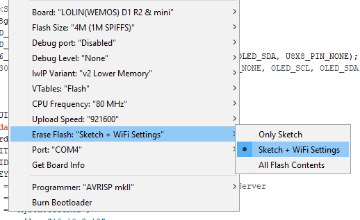
In the Arduino IDE choose Tools, Erase Flash, All Flash Contents.then upload your code.
Pete.
So, is that like a Mazda Ranger pickup ![]()
I don’t think it matters if you are using a NodeMCU or a Wemos (LOLIN) D1 Mini as they are both running the same ESP8266 chip…
Your BAUD rate in your serial monitor needs to match your sketch and in the IDE you can chose this option

My ESP8266 is connected to my WiFi network and the device is connected to Blynk, but Alexa cannot find any new devices? I have two Gen 2 Echo Dots and an Echo Show. What could be the issue here?
What skill needs to be enabled for Amazon Alexa? My device is online and connected to Blynk but Alexa cannot find any new devices. I am really stumped. I hope someone can help.
In the serial monitor I get this:
*WM: Request redirected to captive portal
*WM: Handle root
*WM: WiFi save
*WM: Sent wifi save page
*WM: Connecting to new AP
*WM: Connecting as wifi client…
*WM: Connection result:
*WM: 3
*WM: freeing allocated params!
And after that nothing more…

