I recently ordered another one of these smart sockets from eBay and the seller sent me a different type which
doesn’t have the USB socket on the bottom and the push switch is on the side rather than the top.
As the product wasn’t as advertised I received a refund, but the seller didn’t want to pay the return postage so I had a different type of smart socket to play with. Here are the details…
The model number is SA-P202A and you can find them on Aliexpress here:
Once again, I didn’t bother trying the dedicated app, instead I set about trying to figure out how to flash it with my own firmware.
Disassembly is very similar to the socket shown above, digging out the plastic cover between the mains pins reveals two screws and when these are removed the cover lifts off.
This version of the smart socket also uses a daughterboard module that contains the MCU, but the module is different to the one in the previous smart socket. In this case the MCU is an ESP8285, but I was only able to find that out because I found a data sheet for the module, which is here:
The easiest way to access the connections needed to flash the smart socket is to remove the whole circuit board from the bottom part of the housing and to do this the two screws that attach the board to the mains pins need to be removed. This needs a fairly slim Phillips/Pozidrive screwdriver and once the screws are removed there are a few very poor quality plastic clips that also hold the circuit board in position. On the one I had some of these clips were broken already, but they don’t really do much anyway and it’s easy to pop the board out.
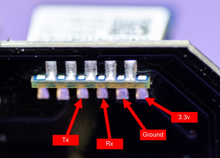
The 4 connections needed to flash the board are all next to each other on the bottom of the daughterboard. The connections are 2mm pitch, but I found that it’s possible to solder a standard 0.1" 4-pin header on to them without too much difficulty.
A bit of work tracing the connections on the circuit board revealed that this smart switch uses different GPIOs for the LED, switch and relay, but because I had the data sheet for the module it was easy to figure these out.
I actually flashed it as an ESP8266 and it worked fine (I didn’t notice that it said in the data sheet that it was an ESP8285 until afterwards) but as far as I can gather the two MCU are effectively the same except that one has onboard memory and the other needs a separate memory chip.
I used the same code as above, but changed the pin definitions as follows:
#define RELAY1     12
#define buttonPin  13
#define BlueLED     5
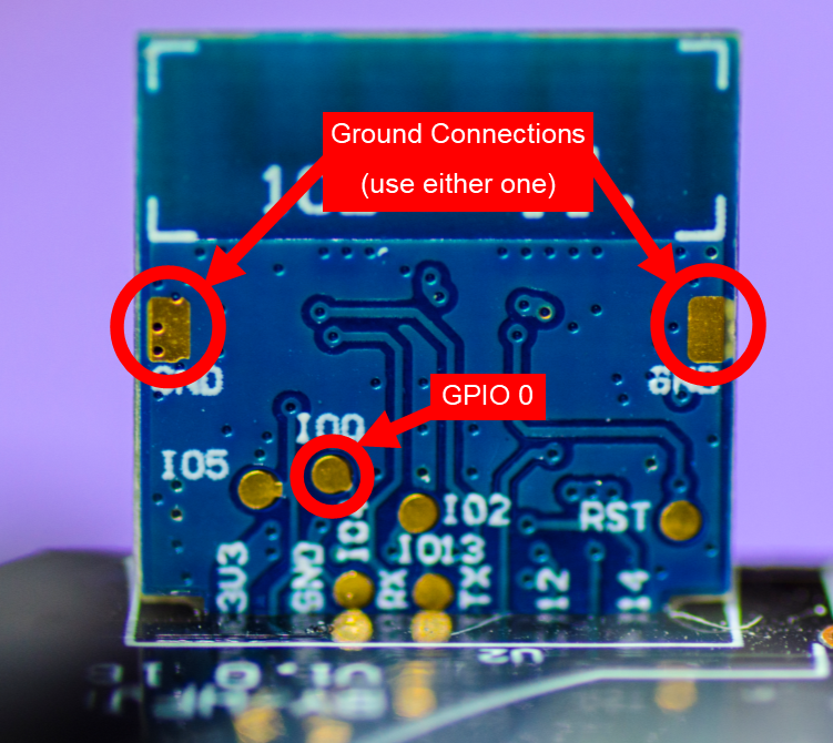
To put the device into flash mode, GPIO0 needs to be shorted to Ground when you apply the 3.3v power from the FTDI adapter. The location of the GPIO0 and Ground connections are easy to spot, but I’ve marked them on the photo below…
Once again,  DO NOT APPLY MAINS VOLTAGE TO THE SMART SOCKET WHILE YOU’RE ATTEMPTING TO RE_FLASH IT!!
After I’d flashed the new code, which includes OTA routines, and tested that it was connecting to Wi-Fi I de-soldered the 4 pin header and re-assembled everything.
Although the LED and switch work fine when it’s being powered from the FTDI, the relay won’t work until the device is receiving mains power, so don’t worry about not hearing the relay clicking in and out at the initial testing stage. It seems that the the 5v feed for the relay is opto-isolated from the 3.3v supply for the ESP module, so reverse-powering the relay via a 3.3v supply won’t work.
Apart from the fact that these smart sockets don’t have the unswitched USB output, they are very similar to the original smart switch. I think the styling of the original one is nicer, and I prefer the push button to be on the top rather than the side, but otherwise there’s very little to choose between them.
It’s slightly easier to flash this style of socket, as the 4 pins are next to each other, but as this only needs to be done once it doesn’t really make much difference provided that you have reasonable soldering skills.
Pete.