and now to add to it both temperature probeshave failed again. i cant get any reading from them now apart from -127.
heres my latest code
#define BLYNK_PRINT Serial // Enables Serial Monitor
#include <SPI.h>
#include <Ethernet.h>
#include <BlynkSimpleEthernet.h> // This part is for Ethernet stuff
#define W5100_CS 10
#define SDCARD_CS 4
#include <TimeLib.h>
#include <WidgetRTC.h>
#define BLYNK_NO_BUILTIN // Disable Apps built-in analog & digital pin operations
#include <SimpleTimer.h>
char auth[] = "********************************"; // Put your Auth Token here.
BlynkTimer timer;
WidgetRTC rtc;
WidgetTerminal terminal(V59);
//Temperature
#include <OneWire.h> // Get 1-wire Library here: http://www.pjrc.com/teensy/td_libs_OneWire.html
//Get DallasTemperature Library here: http://milesburton.com/Main_Page?title=Dallas_Temperature_Control_Library
#include <DallasTemperature.h>
/*-----( Declare Constants and Pin Numbers )-----*/
#define ONE_WIRE_BUS 48// DS18B20 on arduino pin
OneWire oneWire(ONE_WIRE_BUS);
DallasTemperature DS18B20(&oneWire);
// This function will run every time Blynk connection is established
DeviceAddress Probe01 = {0x28, 0x47, 0x27, 0x7C, 0x32, 0x14, 0x01, 0xE5};
DeviceAddress Probe02 = {0x28, 0x39, 0x3C, 0x72, 0x32, 0x14, 0x01, 0x77};
float tanktemp;
float sumptemp;
float tempaver;
BLYNK_CONNECTED() {
rtc.begin();
// Request Blynk server to re-send latest values for all pins
Blynk.syncAll();
}
//ATO switches and relay
byte lowWaterPin = 6; // Goes LOW when water below switch
byte highWaterPin = 7; // Goes LOW when water below switch
byte pumpPin = 8; // Relay to control the water pump
unsigned long maxRunTime = 60 * 1000L; // pump on for max of one minute
unsigned long minOffTime = 1000L; // pump must be off for at least one hour add 60 * 60 *
unsigned long switchDebounceTime = 3 * 1000L; // Switch must be activated for at least 3 seconds.
unsigned long lastPumpTime = 0;
unsigned long lastLowWaterDetectTime = 0;
boolean lastLowWaterState = HIGH;
boolean pumpRunning = false;
unsigned long currentMillis;
////////////////////////////////////////////////////////////////////////////////////
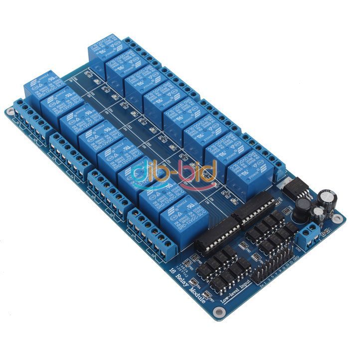
int relayPin = 49;// Heater on ssr1
int relay2Pin = 28;// Cooling to 16ch relay board relay 7 on the board
int relay3Pin = 22;// return pump on relay 1 on the board
int relay4Pin = 23;// Skimmer on relay 2 on the board
int relay5Pin = 24;// Reactor on relay 3 on the board
int relay6Pin = 27;// t5s
int relay7Pin = 26;// fuge light
int relay8Pin = 25;// UV, swapped pin with t5's for testing
int relay9Pin = 29;// leds relay
int wave1Pin = 47;// Wave maker on ssr2
int wave2Pin = 46;// Wavemaker 2 on ssr3
///////////////////////////////////////////////////////////////////////////////////
float desiredTemp = 25;// Set this to your desired temp
float tempDiff = 1;// This variable provides a small +/- temp differential that will prevent constant relay switching.
bool tempAlarmFlag = false; //flag to alarm, and avoid multiple Notification
bool faultyProbeFlag = false; //flag to alarm, and avoid multiple Notification
float lowAlarm = NAN;
float highAlarm = NAN;
int x;
int y;
int tempfail = 0;
int ledStatus = 0;
bool ONstatusleft = false;
bool ONstatusright = false;
int CounterOn = 0;
int CounterOff = 0;
int wavesw = 1;// Wave maker Onoff Button
int heatersw = 1;// Heater Onoff Button
int coolingsw = 1;// Cooling switch
int CurrentPage = 0; // Create a variable to store which page is currently loaded
char Date[16];
char Time[16];
long startseconds = 0; // start time in seconds
long stopseconds = 0; // stop time in seconds
long nowseconds = 0; // time now in seconds
long fadetimemillis = 0;
int minPWM = 0;// variable for min PWM value. keep at 1 to avoid crashing the ledFade()
int leddimming;
int ledbrighten;
int leddimming1;
int ledbrighten1;
int fadeseconds;
int manualleds = 0; // button value
byte fadeIncrement = 1; //How smooth to fade? Uses all 4095 steps available.
int fadetime = 0;
int maxPWM0 = 0; // variable for max PWM value attached to BLYNK Virtual pin.
int maxPWM1 = 0; // variable for max PWM value attached to BLYNK Virtual pin.
int currentFadePosition0 = 0;// don't change this!
int currentFadePosition1 = 0;// don't change this!
unsigned long previousFadeMillis0;// millis() timing Variable, just for fading
unsigned long previousFadeMillis1;// millis() timing Variable, just for fading
long stepWaitTime0 = 0; //How long to watch the clock before incrementing to the next step. (time in milliseconds)
long stepWaitTime1 = 0; //How long to watch the clock before incrementing to the next step. (time in milliseconds)
int desiredledLevel0 = 0;
int desiredledLevel1 = 0;
#define led0 2 // white leds on pin...
#define led1 3 // blue leds on pin...
// LED light control
void setLed() {
stepWaitTime0 = (fadetimemillis / maxPWM0);
stepWaitTime1 = (fadetimemillis / maxPWM1);
terminal.print("current fade position =");
terminal.println(currentFadePosition0);
terminal.print("current fade position1 =");
terminal.println(currentFadePosition1);
}
void ledbright(){
if (nowseconds > startseconds && nowseconds < stopseconds) {
currentFadePosition0 = currentFadePosition0 + fadeIncrement;
if (currentFadePosition0 >= maxPWM0) {
// At max limit stop the fade
currentFadePosition0 = maxPWM0;
}
// put actionable () here.
analogWrite(led0, currentFadePosition0);
}
}
void leddim(){
if (nowseconds > stopseconds)
currentFadePosition0 = currentFadePosition0 - fadeIncrement;
if (currentFadePosition0 <= minPWM) {
// At min limit stop the fade
currentFadePosition0 = minPWM;
}
// put actionable () here
analogWrite(led0, currentFadePosition0);
}
void ledbright1(){
if (nowseconds > startseconds && nowseconds < stopseconds) {
currentFadePosition1 = currentFadePosition1 + fadeIncrement;
if (currentFadePosition1 >= maxPWM1) {
// At max limit stop the fade
currentFadePosition1 = maxPWM1;
}
// put actionable () here.
analogWrite(led1, currentFadePosition1);
// reset millis for the next iteration (fade timer only)
}
}
void leddim1(){
if (nowseconds > stopseconds)
currentFadePosition1 = currentFadePosition1 - fadeIncrement;
if (currentFadePosition1 <= minPWM) {
// At min limit stop the fade
currentFadePosition1 = minPWM;
Blynk.virtualWrite(V57, LOW);// turns LED relay on
Blynk.virtualWrite(V58, HIGH);// turns fuge light off
Blynk.syncVirtual(V58, V57);
}
// put actionable () here
analogWrite(led1, currentFadePosition1);
}
// Digital clock display of the time
void clockDisplay(){
String currentTime = String(hour()) + ":" + minute() + ":" + second();
String currentDate = String(day()) + " " + month() + " " + year();
nowseconds = ((hour() * 3600) + (minute() * 60) + second());
Serial.print("Time =");
Serial.println(currentTime);
// Serial.println(currentDate);
Serial.print("Nowseconds =");
Serial.println(nowseconds);
// Serial.print("Start = ");
// Serial.println(startseconds);
//Serial.print("Stop = ");
// Serial.println(stopseconds);
// Serial.print("fade position0 =");
// Serial.println(currentFadePosition0);
// Serial.println();
// Send time to the App
Blynk.virtualWrite(V0, currentTime);
// Send date to the App
//Blynk.virtualWrite(V2, currentDate);
}
BLYNK_WRITE(V10) {// slider widget to set the maximum led level from the Blynk App.
desiredledLevel0 = param.asInt();// channel 1
maxPWM0 = map(desiredledLevel0, 0, 100, minPWM, 255);
}
BLYNK_WRITE(V13) {// slider widget to set the maximum led level from the Blynk App.
desiredledLevel1 = param.asInt();// channel 2
maxPWM1 = map(desiredledLevel1, 0, 100, minPWM, 255);
}
BLYNK_WRITE(V14) {// slider widget to set the led fade duration up tp 3 hours.
fadetime = param.asInt();
fadeseconds = map(fadetime, 1, 180, 1, 10800);// 3 hour fade duration is max seconds
fadetimemillis = map(fadetime, 1, 180, 1L, 10800000L);// 3 hour fade duration is max
// Serial.print("Fade Time in seconds =");
// Serial.println(fadetimeseconds);
}
void activetoday() { // check if schedule should run today
if (year() != 1970) {
Blynk.syncVirtual(V15); // sync led timeinput widget
Blynk.syncVirtual(V16);// sync T5s timeinput widget
sprintf(Date, "%02d/%02d/%04d", day(), month(), year());
sprintf(Time, "%02d:%02d:%02d", hour(), minute(), second());
nowseconds = ((hour() * 3600) + (minute() * 60) + second());
}
}
BLYNK_WRITE(V58){ //fuge relay buton
int fuge = param.asInt(); // Get State of Virtual Button, fuge
if (fuge == 1) {
digitalWrite(relay7Pin,LOW);
}
else
{
digitalWrite(relay7Pin,HIGH);
}
}
BLYNK_WRITE(V57){ //leds relay buton
int ledr = param.asInt(); // Get State of Virtual Button
if (ledr == 1) {
digitalWrite(relay9Pin,LOW);
}
else
{
digitalWrite(relay9Pin,HIGH);
}
}
BLYNK_WRITE(V17){ //T5's relay buton
int tube = param.asInt(); // Get State of Virtual Button, t5s
if (tube == 1) {
digitalWrite(relay6Pin,LOW);
}
else
{
digitalWrite(relay6Pin,HIGH);
}
}
BLYNK_WRITE(V18){ //manual auto lights button
int man = param.asInt(); // Get State of Virtual Button, manual lights
manualleds = man;
if (man == 1) {
timer.disable(ledbrighten);
timer.disable(ledbrighten1);
timer.disable(leddimming);
timer.disable(leddimming1);
analogWrite(led0, maxPWM0);
analogWrite(led1, maxPWM1);
}
else
{
timer.enable(ledbrighten);
timer.enable(ledbrighten1);
timer.enable(leddimming);
timer.enable(leddimming1);
analogWrite(led0, currentFadePosition0);
analogWrite(led1, currentFadePosition1);
}
}
BLYNK_WRITE(V16) { // T5s
TimeInputParam t(param);
int startsecond = (t.getStartHour() * 3600) + (t.getStartMinute() * 60);
int stopsecond = (t.getStopHour() * 3600) + (t.getStopMinute() * 60);
Serial.print("Start = ");
Serial.println(startsecond);
Serial.print("Stop = ");
Serial.println(stopsecond);
Serial.println();
int dayadjustment = -1;
if(weekday() == 1){
dayadjustment = 6; // needed for Sunday Time library is day 1 and Blynk is day 7
}
if(t.isWeekdaySelected((weekday() + dayadjustment))){ //Time library starts week on Sunday, Blynk on Monday
//Schedule is ACTIVE today
if(nowseconds >= startsecond - 31 && nowseconds <= startsecond + 31 ){ // 62s on 60s timer ensures 1 trigger command is sent
Serial.println("Schedule 1 started");
Blynk.virtualWrite(V17, HIGH); // turn on virtual button t5s
Blynk.syncVirtual(V17);
}
if(nowseconds >= stopsecond - 31 && nowseconds <= stopsecond + 31 ){ // 62s on 60s timer ensures 1 trigger command is sent
Serial.println("Schedule 1 finished");
Blynk.virtualWrite(V17, LOW); // turn OFF virtual vutton t5s
Blynk.syncVirtual(V17);
}
}
}
BLYNK_WRITE(V15) {// set time for leds
TimeInputParam t(param);
// Serial.print("Checked schedule at: ");
// Serial.println(Time);
int dayadjustment = -1;
if (weekday() == 1) {
dayadjustment = 6; // needed for Sunday, Time library is day 1 and Blynk is day 7
}
if (t.isWeekdaySelected((weekday() + dayadjustment))) { //Time library starts week on Sunday, Blynk on Monday
// Serial.println("Schedule ACTIVE today");
nowseconds = ((hour() * 3600) + (minute() * 60) + second());
startseconds = (t.getStartHour() * 3600) + (t.getStartMinute() * 60);
if (nowseconds >= startseconds) {
if (nowseconds <= startseconds + 90) { // 90s on 60s timer ensures 1 trigger command is sent
// code here
Serial.println("Schedule 2 started");
ledbrighten = timer.setTimer(stepWaitTime0, ledbright, maxPWM0);
ledbrighten1 = timer.setTimer(stepWaitTime1, ledbright1, maxPWM1);
Blynk.virtualWrite(V57, HIGH);// turns LED relay on
Blynk.virtualWrite(V58, LOW);// turns fuge light off
Blynk.syncVirtual(V58, V57);
}
}
else {
// Serial.println("Relay not on");// nothing more to do here, waiting for relay to be turned on later today
}
stopseconds = (t.getStopHour() * 3600) + (t.getStopMinute() * 60);
if (nowseconds >= stopseconds) {
// 90s on 60s timer ensures 1 trigger command is sent
if (nowseconds <= stopseconds + 90) {
// code here
leddimming = timer.setTimer(stepWaitTime0, leddim, maxPWM0);
leddimming1 = timer.setTimer(stepWaitTime1, leddim1, maxPWM1);
}
}
else {
if (nowseconds >= startseconds) { // only show if motor has already started today
// Serial.println("Relay is still ON");
// nothing more to do here, waiting for motor to be turned off later today
}
}
}
else {
// Serial.println("Schedule INACTIVE today");
// nothing to do today, check again in 1 minutes time
}
// Serial.println();
}
void reconnectBlynk() {
if (!Blynk.connected()) {
if (Blynk.connect()) {
BLYNK_LOG("Reconnected");
}
else {
BLYNK_LOG("Not reconnected");
}
}
}
//WAVEMAKERS CONTROLE
BLYNK_WRITE(V4){ // wave on time slider
x = param.asInt();
}
BLYNK_WRITE(V7){ // wave Off time slider
y = param.asInt(); // set variable as Slider value
}
WidgetLED leftled(V68);
WidgetLED rightled(V69);
void wavecontrol(){
if((CounterOn > 0)&& (ONstatusleft == true)){
CounterOn--; // reduce Countdown by 1 minute every 60s
}
if((CounterOn > 0) && (ONstatusleft == false)){
ONstatusleft = true; // to ensure device is only turned ON once
CounterOff = 0;
digitalWrite(wave1Pin,HIGH);
leftled.on();
}
if((CounterOn == 0) && (ONstatusleft == true)){
ONstatusleft = false; // to ensure device is only turned OFF once
digitalWrite(wave1Pin,LOW);
leftled.off();
}
if ((CounterOff == 0) && (CounterOn == 0))
{
CounterOff = x;
}
if((CounterOff > 0)&& (ONstatusright == true)){
CounterOff--; //
}
if((CounterOff > 0) && (ONstatusright == false)){
ONstatusright = true; // to ensure device is only turned ON once
CounterOn = 0;
digitalWrite(wave2Pin,HIGH);
rightled.on();
}
if((CounterOff == 0) && (ONstatusright == true)){
ONstatusright = false; // to ensure device is only turned OFF once
digitalWrite(wave2Pin,LOW);
rightled.off();
}
if ((CounterOn == 0) && (CounterOff == 0))
{
CounterOn = y;
}
}
BLYNK_WRITE(V6) // wavemakers
{
int wavesw = param.asInt(); // Get State of Virtual Button, wave makers
if (wavesw == 1) {
Blynk.virtualWrite(V4,5);
Blynk.virtualWrite(V7,5);
Blynk.syncVirtual(V4, V7);
}else{
Blynk.virtualWrite(V4,0);
Blynk.virtualWrite(V7,0);
Blynk.syncVirtual(V4, V7);
digitalWrite(wave1Pin,LOW);
digitalWrite(wave2Pin,LOW);
}
}
BLYNK_WRITE(V60) // left wave button
{
int leftwavesw = param.asInt(); // Get State of Virtual Button, wave makers
if (leftwavesw == 1) {
Blynk.virtualWrite(V7,5);
Blynk.syncVirtual(V7);
}else{
Blynk.virtualWrite(V7,0);
Blynk.syncVirtual(V7);
}
}
BLYNK_WRITE(V61) // right wave button
{
int rightwavesw = param.asInt(); // Get State of Virtual Button, wave makers
if (rightwavesw == 1) {
Blynk.virtualWrite(V4,5);
Blynk.syncVirtual(V4);
}else{
Blynk.virtualWrite(V4,0);
Blynk.syncVirtual(V4);
}
}
//TEMPERATURE CONTROL
WidgetLED heaterled(V63);
WidgetLED coolerled(V64);
BLYNK_WRITE(V8){ // heater button
int heatersw = param.asInt(); // Get State of Virtual Button, heater
}
BLYNK_WRITE(V9){
int coolingsw = param.asInt(); // Get State of Virtual Button, cooling
}
BLYNK_WRITE(V11)
{
//reads the setppoint
desiredTemp = param.asFloat();
}
BLYNK_WRITE(V12)
{
//reads the differential
tempDiff = param.asFloat();
}
BLYNK_WRITE(V32){
//reads low alarm
lowAlarm = param.asFloat();
}
BLYNK_WRITE(V33){
//reads high alarm
highAlarm = param.asFloat();
}
void Heater()
{
//if sensor not sending temperature turn relay OFF for safety
if (tanktemp == -127) {
digitalWrite(relayPin, LOW);
heaterled.off();
}
else if (tanktemp < desiredTemp - tempDiff)
{
Serial.print("tanktemper");
Serial.println(tanktemp);
Serial.print("desired");
Serial.println(desiredTemp);
Serial.print("temp Diff");
Serial.println(tempDiff);
digitalWrite(relayPin, HIGH);
heaterled.on();
}
else{
digitalWrite(relayPin, LOW);
heaterled.off();
}
if (tanktemp >= desiredTemp )
{
digitalWrite(relayPin, LOW);
heaterled.off();
}
}//--(end Heater )---
void Cooler()
{
if (tanktemp == -127.00 && 80)
{
digitalWrite(relay2Pin, HIGH);
coolerled.off();
}
else if (tanktemp > desiredTemp + tempDiff)
{
digitalWrite(relay2Pin, LOW);
coolerled.on();
}
if (tanktemp < desiredTemp )
{
digitalWrite(relay2Pin, HIGH);
coolerled.off();
}
if (tempfail >= 3)
{
digitalWrite(relay2Pin, HIGH);
coolerled.off();
}
}//--(end Cooler )---
void relaysOn()
{
Blynk.virtualWrite(V2, HIGH);// Skimmer
Blynk.virtualWrite(V3, HIGH);// Reactor
Blynk.virtualWrite(V6,HIGH);// wavemakers
Blynk.virtualWrite(V8, HIGH);// Heaters
Blynk.virtualWrite(V9, HIGH);// cooling
Blynk.syncVirtual(V2, V3, V6, V8, V9); // Trigger the associated function for V6 as if you had touched the widget in the App
}
void take_temp_readings() {
//Serial.print("Number of Devices found on bus = ");
//Serial.println(DS18B20.getDeviceCount());
//Serial.print("Getting temperatures... ");
//Serial.println();
// DS18B20.requestTemperatures();
DS18B20.requestTemperaturesByAddress(Probe01);
DS18B20.requestTemperaturesByAddress(Probe02);
if (tanktemp == -127.00)
{
Serial.println("Error getting temperature ");
tempfail+1;
}
}
void send_data_to_blynk(){
//tanktemp = DS18B20.getTempCByIndex(0);
// Get the temperature that you told the sensor to measure
// DS18B20.requestTemperaturesByAddress(Probe01); // Send the command to get temperatures
tanktemp = DS18B20.getTempC(Probe01);
//if (tanktemp == -127) {
// tempfail+1;
//} else {
Blynk.virtualWrite(V5, tanktemp); // send tank temp to virtual pin 5
//}
sumptemp = DS18B20.getTempC(Probe02);
//sumptemp = DS18B20.getTempCByIndex(1);
// if (sumptemp == -127) {
// tempfail+1;
// } else {
Blynk.virtualWrite(V56, sumptemp); // send sump temp to virtual pin 56
// }
tempaver = tanktemp + sumptemp / 2;
Blynk.virtualWrite(V70, tempaver); // send average temp to virtual pin 70
//check alarms;
if (isnan(tanktemp)){
if (Blynk.connected() && !faultyProbeFlag)
{
Blynk.notify("Probe disconnected");
Blynk.email("A.bundy1995@hotmail.co.uk", "Aquaruim Controler Alert", "Probe disconnected");
faultyProbeFlag = true;
}
}
else if ((tanktemp < lowAlarm && !tempAlarmFlag) && (tempfail >= 3)){
Blynk.notify(String(tanktemp) + "ºC Low temp alarm");
Blynk.email("A.bundy1995@hotmail.co.uk", "Aquaruim Controler Alert", (String(tanktemp) + "ºC Low temp alarm"));
tempAlarmFlag = true;
tempfail = 0;
}
else if (tanktemp > highAlarm && !tempAlarmFlag){
Blynk.notify(String(tanktemp) + "ºC High temp alarm");
Blynk.email("A.bundy1995@hotmail.co.uk", "Aquaruim Controler Alert", (String(tanktemp) + "ºC High temp alarm"));
tempAlarmFlag = true;
}
else if (tanktemp > lowAlarm && tanktemp < highAlarm)
{
tempAlarmFlag = false;
}
else faultyProbeFlag = false;
}
WidgetLED sumphighled(V65);
WidgetLED sumplowled(V49);
WidgetLED atovalveled(V66);
void ATOcontrol()
{
boolean lowWaterState = digitalRead(lowWaterPin);
boolean highWaterState = digitalRead(highWaterPin);
if(lowWaterState != lastLowWaterState){
lastLowWaterDetectTime = currentMillis;
sumplowled.on();
}
if (highWaterState == LOW)
{
sumphighled.on();
}
else {
sumphighled.off();
}
if (lowWaterState == LOW)
{
sumplowled.on();
}
else {
sumplowled.off();
}
if ((lowWaterState == LOW) && (highWaterState == HIGH)){
Blynk.notify(String(lowWaterState) + "Low level floatswitch fail");
Blynk.email("A.bundy1995@hotmail.co.uk", "Aquaruim Controler Alert", (String(lowWaterState) + "Low level floatswitch fail")); //send alarm
}
if (pumpRunning) { // if the pump is on then let's see if we should turn it off yet
if ((highWaterState == HIGH) || (currentMillis - lastPumpTime >= maxRunTime)){
atovalveled.off();
digitalWrite(pumpPin, LOW);
pumpRunning = false;
lastPumpTime = currentMillis;
}
}
else { // pump is not running, see if we need to turn it on
if((lowWaterState == LOW) && (highWaterState == LOW) && (currentMillis - lastLowWaterDetectTime >= switchDebounceTime) && (currentMillis - lastPumpTime > minOffTime)){ // switch is low and has been for at least 3 seconds
atovalveled.on();
digitalWrite(pumpPin, HIGH);
pumpRunning = true;
lastPumpTime = currentMillis;
}
}
lastLowWaterState = lowWaterState;
}
// BUTTON INPUTS
BLYNK_WRITE(V3){ // Reactor button off
int reactor = param.asInt(); // Get State of Virtual Button, Return pump
if (reactor == 1) { // button ON
// Turn as many pins/relays ON as you need
digitalWrite(relay5Pin, LOW);
} else { // button OFF
// Turn as many pins/relays OFF as you need
digitalWrite(relay5Pin, HIGH);
}
}
BLYNK_WRITE(V2){ // Skimmer button off
int skimmer = param.asInt(); // Get State of Virtual Button, Return pump
if (skimmer == 1) { // button ON
// Turn as many pins/relays ON as you need
digitalWrite(relay4Pin, LOW);
} else { // button OFF
// Turn as many pins/relays OFF as you need
digitalWrite(relay4Pin, HIGH);
}
}
BLYNK_WRITE(V62){ // UV button off
int uv = param.asInt(); // Get State of Virtual Button, Return pump
if (uv == 1) { // button ON
// Turn as many pins/relays ON as you need
digitalWrite(relay8Pin, LOW);
} else { // button OFF
// Turn as many pins/relays OFF as you need
digitalWrite(relay8Pin, HIGH);
}
}
BLYNK_WRITE(V1){ // Return pump button off
int value = param.asInt(); // Get State of Virtual Button, Return pump
if (value == 1) { // button ON
// Turn as many pins/relays ON as you need
digitalWrite(relay3Pin, LOW);
// bt0.setValue(&number5);
timer.setTimeout(30000, relaysOn);
} else { // button OFF
// Turn as many pins/relays OFF as you need
digitalWrite(relay3Pin, HIGH);
digitalWrite(relay4Pin, HIGH);
Blynk.virtualWrite(V2, LOW);// Skimmer
digitalWrite(relay5Pin, HIGH);
Blynk.virtualWrite(V3, LOW);// Reactor
Blynk.virtualWrite(V6, LOW);// Wavemakers
Blynk.syncVirtual(V6); // Trigger the associated function for V6 as if you had touched the widget in the App
Blynk.virtualWrite(V8, LOW);// Heating
Blynk.virtualWrite(V9, LOW);// Cooling
Blynk.syncVirtual(V9);
}
}
BLYNK_WRITE(V38){ // feed button to turn relays off for set time then back on again
int value = param.asInt(); // Get State of Virtual Button, Return pump
if (value == 1) { // button Pressed
// Turn as many pins/relays OFF as you need
Blynk.virtualWrite(V2, LOW);// Skimmer
Blynk.virtualWrite(V3, LOW);// Reactor
Blynk.virtualWrite(V62, LOW);// uv
Blynk.virtualWrite(V6, LOW);// Wavemakers
Blynk.virtualWrite(V8, LOW);// heaters
Blynk.virtualWrite(V9, LOW);// cooling
Blynk.syncVirtual(V2, V3, V6, V8, V9); // Trigger the associated function for V6 as if you had touched the widget in the App
timer.setTimeout(420000L, relaysOn);// wait for 7 mins before turning everything back on.
Blynk.virtualWrite(V1, HIGH);
Blynk.syncVirtual(V1);
}
}
void setup() /****** SETUP: RUNS ONCE ******/
{
Serial.begin(9600); // start serial port to show results
// run timer every minute to check for led On/Off action
DS18B20.begin(); // Initialize the Temperature measurement library
// set the resolution to 10 bit (Can be 9 to 12 bits .. lower is faster)
DS18B20.setResolution(Probe01, 11);
DS18B20.setResolution(Probe02, 11);
// DS18B20.setWaitForConversion(false); // make reading NON blocking
pinMode(relayPin, OUTPUT);
digitalWrite(relayPin, HIGH);
pinMode(relay2Pin, OUTPUT);// Cooling
digitalWrite(relay2Pin, HIGH);
pinMode(relay3Pin, OUTPUT);//return pump
digitalWrite(relay3Pin, HIGH);
pinMode(relay4Pin, OUTPUT);// skimmer
digitalWrite(relay4Pin, HIGH);
pinMode(relay5Pin, OUTPUT);// reactor
digitalWrite(relay5Pin, HIGH);
pinMode(wave1Pin, OUTPUT);
pinMode(wave2Pin, OUTPUT);
pinMode(relay6Pin, OUTPUT);// t5s declaired
digitalWrite(relay6Pin, HIGH);
pinMode(relay7Pin, OUTPUT);// Fuge light
digitalWrite(relay7Pin, HIGH);
pinMode(relay8Pin, OUTPUT);// UV
digitalWrite(relay8Pin, HIGH);
pinMode(relay9Pin, OUTPUT);// leds relay
digitalWrite(relay9Pin, HIGH);
pinMode(SDCARD_CS, OUTPUT);
digitalWrite(SDCARD_CS, HIGH); // Deselect the SD card
pinMode(lowWaterPin, INPUT_PULLUP);// ATO
pinMode(highWaterPin, INPUT_PULLUP);//ATO
pinMode(pumpPin, OUTPUT);// ATO
///////////////////////////////////////////////////////////////////////////////
Blynk.begin(auth); // Here your Arduino connects to the Blynk Cloud.
timer.setInterval(1000L, clockDisplay); // digital time displayed every second
timer.setInterval(1040L, setLed);
timer.setInterval(1080L, wavecontrol);
timer.setInterval(1120L, ATOcontrol);
timer.setInterval(2500L, take_temp_readings); // Setup a function to be called every second
timer.setInterval(5000L, send_data_to_blynk);
timer.setInterval(5100L, Heater);
timer.setInterval(5200L, Cooler);
timer.setInterval(60000L, activetoday); // check every minute if schedule should run today
timer.setInterval(6020L, reconnectBlynk); // check every 60s if still connected to server
}//--(end setup )---
void loop() /****** LOOP: RUNS CONSTANTLY ******/
{
Blynk.run(); // All the Blynk Magic happens here...
timer.run(); // Initiates BlynkTimer
// get the current time, for this time around loop
// all millis() timer checks will use this time stamp
currentMillis = millis();
}//--(end main loop )---
//*********( THE END )***********
I honestly dont get where am going wrong now. Begining to get fed up with something that should have been simple.


 but i still have the issue when i trigger the relay with the fuge light connected, i get -127. if i disconnect the light with the relay still active, the temperature readings return to normal.
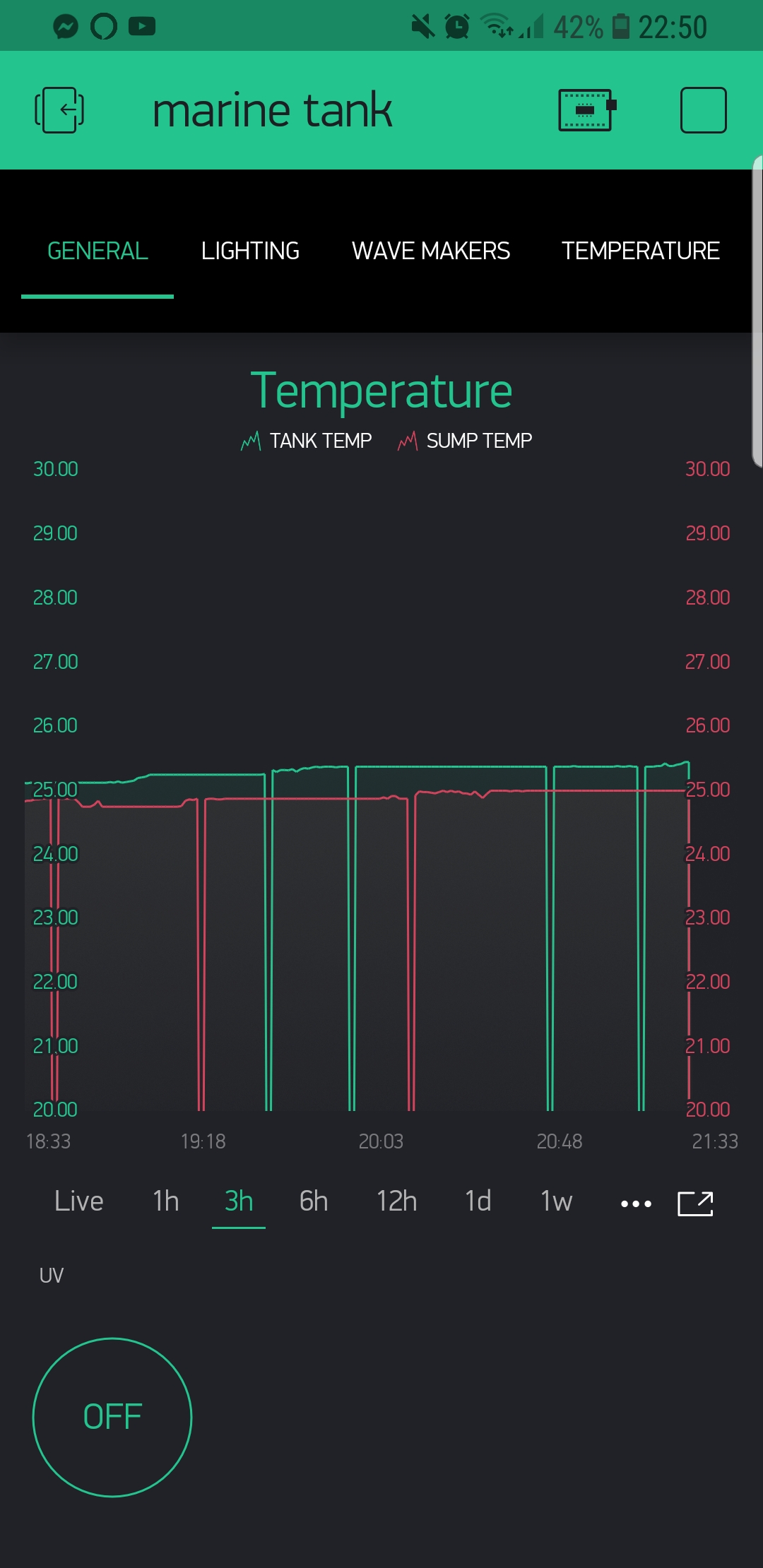
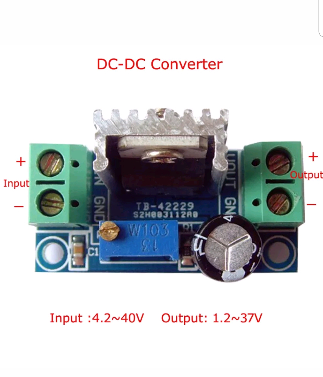
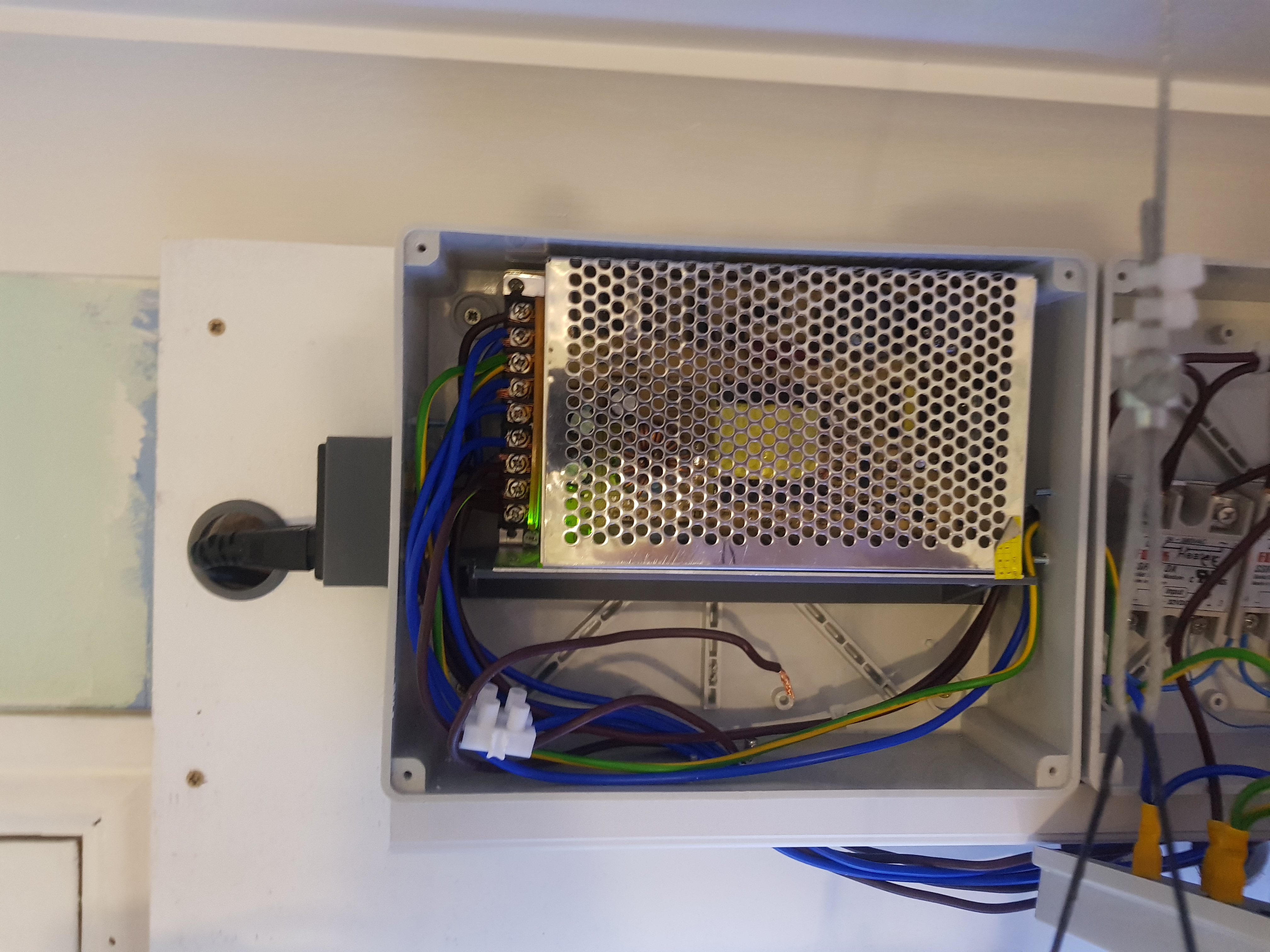
 also changed iver to another power supply, so far so good