Adding GSM GPRS conectivity to ArduFarmBot 2 NodeMCU

Hi,

I’m newbie in this field so please be patient with me.
I managed to get this project working as described:


Full code is here:

All is good HOWEVER the place when I intend to use it doesn’t have WiFi hot spot and I want to be able to add GSM/GPRS connectivity so I can remotely control things.
I bought a SIM900 module which I was able to get running (with some tweaks) using the TinyGSM example from Ardiono IDE. With this I reached my top level of competence in this field so far.
My questions are:
1/ Can this project run simultaneously WiFi AND GSM/GPRS?
2/ What needs to be done if answer to is 1/ Yes and No?
3/ Do I need to move the buttons connected to Tx/Rx other pins or I can connect the SIM900 module there like it is?
Any help would be greatly appreciated.

Not without significant modification. Of there is no WiFi in the area of use then modify the code to use GPRS only.

It depends how you want to connect the SIM900 and whether you can debug the code without any serial monitor debugging (which requires the Tx pin to be free at the very least).
You can create a SoftwareSerial port using any two available (and suitable) pins, but having had a very quick look at the code it seems that there is already quite a lot happening and you may not have suitable pins available.

A better option may be to use an ESP32, probably with a built-in SIM card slot such as the TTGO-CALL.

That’s not a massively difficult task, as the two devices are very similar in many ways.
The thing you should be aware of is that ant SIM800/900 board (whether it’s built into an ESP32 board or stand-alone) requires quite a bit of current to work successfully. I’m not sure how you’re planning to power this project, but if there is mains power available then maybe you should look at a way of getting WiFi to that location, maybe via a power line adapter.

Pete.

Thanks for your quick reply.

Not without significant modification. Of there is no WiFi in the area of use then modify the code to use GPRS only.

If I have to choose I would prefer to have GPRS connection only.

You can create a SoftwareSerial port using any two available (and suitable) pins, but having had a very quick look at the code it seems that there is already quite a lot happening and you may not have suitable pins available.

Yes, I realized that I’ll need some more pins available for this. I was able to move one of the buttons to D0 (didn’t work on D8 which I learned is pulled low and must stay so at powerup) but I’ll need one more for debug purposes. I learned that GPIO9 and 10 are not usable unless the ESP8266 is flashed in DIO mode and that will effectively free only of them to be used as I/O pin. Is that an option?

A better option may be to use an ESP32, probably with a built-in SIM card slot such as the TTGO-CALL.

Since I’m new in this field I would prefer to keep it simple for now.

I have mains power line at the location so powering things is not an issue.

I’ve never heard of this, as far as I’m concerned they are reserved pins, but they do seemed to be used for buttons in the sketch.

You should probably read this:

You’re actually making it more complicated by sticking with the ESP8266 rather than the ESP32.

Pete.

I understand that ESP32 is more capable but I wanted to start with a project that is complete and that I can copy easily at the same time hence the choice of NodeMCU.
Also considering my limited knowledge and skills I’m not sure I’ll be capable to transfer the whole project on ESP32 .

Concerning freeing GPIO9 and 10:


https://bbs.espressif.com/viewtopic.php?t=654

So I we suppose that I can free the Tx/Rx pinsfor the SIM900 module what needs to be done in order to turn this project from WiFi to GPRS?

Yes, I do recall reading that on Pete Scargill’s blog, but as my choice of ESP8266 based board is the Wemos D1 Mini clone it wasn’t of much use to me.

The biggest issue you’ll have is that if you tie-up the Tx pin you won’t have a method of debugging your code. Also, if you tie-up the Rx pin then you won’t be able to do code uploads without disconnecting the hardware from these pins. This wouldn’t normally be an issue, as you could do OTA updates over WiFi, but that’s not going to be possible when just using GPRS.

Is WiFi over mains wiring totally out of the question?

Pete.

I can free up Tx/Rx pins as buttons only are an accessory to this project. I’ll be relying on the automatic mode of this greenhouse controller and once soil moisture sensor is calibrated (automatic watering is main purpose of this project for me) hardly any software changes would be necessary.
WiFi over mains is not out of the question. Just wanted to use what’s already by hand and not spend on another WiFi SIM card router.

Okay, if you can find a way to keep Rx and Tx free, and two other pins to connect the SIM900 to then use SoftwareSerial to create the second UART.
SoftwareSerial is only suitable for speeds up to 9600, so it depends on what the default speed is for your SIM900. If it’s higher than 9600 then you’ll need to chang this using an AT command.

I’d suggest looking at other SIM900/ESP8266 sketches and seeing how to set-up the connection, and maybe run a different example sketch to ensure that you can get your SIM card working correctly with Blynk.

Pete.

I already tried successfully two methods to get the SIM900 going based on the Blynk TinyGSM example for SIM800_SIM900 boards from Arduino IDE (code below).
First one was using SoftwareSerial however this way I’m loosing two more pins.
Second one I connected the SIM900 to Tx/Rx pins but it didn’t work. Then I changed this line:

#define SerialAT Serial1
to
#define SerialAT Serial

/* Comment this out to disable prints and save space */
#define BLYNK_PRINT Serial

// Select your modem:
//#define TINY_GSM_MODEM_SIM800
#define TINY_GSM_MODEM_SIM900
//#define TINY_GSM_MODEM_M590
//#define TINY_GSM_MODEM_A6
//#define TINY_GSM_MODEM_A7
//#define TINY_GSM_MODEM_BG96
//#define TINY_GSM_MODEM_XBEE

// Default heartbeat interval for GSM is 60
// If you want override this value, uncomment and set this option:
//#define BLYNK_HEARTBEAT 30

#include <TinyGsmClient.h>
#include <BlynkSimpleTinyGSM.h>

// You should get Auth Token in the Blynk App.
// Go to the Project Settings (nut icon).
char auth[] = "YourAuthToken";

// Your GPRS credentials
// Leave empty, if missing user or pass
char apn[]  = "YourAPN";
char user[] = "";
char pass[] = "";

// Hardware Serial on Mega, Leonardo, Micro
#define SerialAT Serial1

// or Software Serial on Uno, Nano
//#include <SoftwareSerial.h>
//SoftwareSerial SerialAT(2, 3); // RX, TX

TinyGsm modem(SerialAT);

void setup()
{
  // Debug console
  Serial.begin(9600);

  delay(10);

  // Set GSM module baud rate
  SerialAT.begin(115200);
  delay(3000);

  // Restart takes quite some time
  // To skip it, call init() instead of restart()
  Serial.println("Initializing modem...");
  modem.restart();

  // Unlock your SIM card with a PIN
  //modem.simUnlock("1234");

  Blynk.begin(auth, modem, apn, user, pass);
}

void loop()
{
  Blynk.run();
}

Both ways the module connects to GPRS and Blynk server. With the second method all commands sent to the module are visible in the serial monitor.
I saw a tutorial where the module was sending SMS messages and was connected to the Tx pin only but I’m not sure how that works.

TinyGSM AT_Debug tool determined that baud rate of the module was 115200.

You can’t share the serial port with debug messages and the SIM900, you’ll get an unstable connection and frequent disconnections.

And you can’t use SoftwareSerial above 9600 if you want a stable connection.

Pete.

I managed to free Tx/Rx lines by redirecting the buttons to D0 and GPIO10.
Serial monitor doesn’t output much as it is - only that Blynk is connected so I guess I can give it a shot with the SIM900.

And you can’t use SoftwareSerial above 9600 if you want a stable connection.

Noted!

Tried to insert the GSM example code into the existing one but it looks like it’s not going to be as easy as noted in the example sketch:

void loop()
{
  Blynk.run();
  // You can inject your own code or combine it with other sketches.
  // Check other examples on how to communicate with Blynk. Remember
  // to avoid delay() function!
}

Any guidelines how to proceed further would be appreciated.

Your void loop will remain the same regardless of your connection method.
It’s the included libraries and Blynk connection process that will change.
You should compare a NodeMCU/SIM900 sketch with yours, and maybe run the SIM900 sketch as it stands to verify the connectivity and that your SIM works correctly with Blynk.

Pete.

After some more trial and error inserting the GSM code and some debugging (after carefully reading error messages) I’m happy to announce that GPRS connectivity of this project is now a SUCCESS!
Thank you Pete for your comments and help!

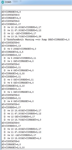
So far the serial monitor looks mostly like this:

From time to time when the pump switches automatically on I get this I guess because of the notifications:

To prevent that maybe I willn delete these:

Blynk.notify("ArduFarmBot2: Warning ==>> Pump ON"); 
Blynk.notify("ArduFarmBot2: Warning ==>> Lamp ON");

I don’t really need them because I have LEDs in Blynk showing what is ON.

I assume the 4 line “breaks” in the serial monitor flow are the packets send to Blynk. Any idea how I can check the size of those so I can figure out daily and monthly MB traffic?

To conclude the topic and in case anyone would like to turn the ArduFarmBot2 into GPRS connected I’m posting the changes I made to the project.

1/ To free GPIO9 and 10 (according to some using GPIO9 is questionable) flash your ESP8266 with the latest firmware in DIO mode.

2/ replace the main code with this one:


/***************************************************************************************************************
 *  ArduFarmBot using NodeMCU ESP-12 Develop Kit V1.0
 *  DHT connected to NodeMCU pin D3 (Ambient Temperature and Relative Humidity)
 *  Soil Moister Sensor connected to A0
 *  Sensor Data on local OLED Display
 *  Local Command via buttons 
 *  OLED Display is off as default. Press Sensor Button to update and display data
 *  Introduced the function "waitButtonPress (int waitTime)", to break initial loop
 *  Automatic Local Control
 *  Display automatic set-up parameters at Start-up
 *  Sensor data sent to Blynk app
 *  Control commands received from Blynk app
 *  Downloads, docs, tutorials: http://www.blynk.cc
 *  Blynk library is licensed under MIT license
 *       
 *  MJRoBot Version 3.0 - Automatic and Remote Control Developed by MJRovai 16 Feb 2017
 ********************************************************************************************************************************/

#define SW_VERSION "   SW Ver. 3.1" // SW version will appears at innitial LCD Display
#include "stationDefines.h"       // Project definitions
#include "stationCredentials.h"

/* ESP & Blynk */
#define BLYNK_PRINT Serial    // Comment this out to disable prints and save space
// Select your modem:
//#define TINY_GSM_MODEM_SIM800
#define TINY_GSM_MODEM_SIM900
//#define TINY_GSM_MODEM_M590
//#define TINY_GSM_MODEM_A6
//#define TINY_GSM_MODEM_A7
//#define TINY_GSM_MODEM_BG96
//#define TINY_GSM_MODEM_XBEE

// Default heartbeat interval for GSM is 60
// If you want override this value, uncomment and set this option:
// #define BLYNK_HEARTBEAT 8

#include <TinyGsmClient.h>
#include <BlynkSimpleTinyGSM.h>

#define SerialAT Serial
TinyGsm modem(SerialAT);

WidgetLED PUMPs(V0);  // Echo signal to Sensors Tab at Blynk App
WidgetLED PUMPa(V5); // Echo signal to Actuators Tab at Blynk App
WidgetLED LAMPs(V1);  // Echo signal to Sensors Tab at Blynk App
WidgetLED LAMPa(V6); // Echo signal to Actuators Tab at Blynk App

/* TIMER */
#include "SimpleTimer.h"
SimpleTimer timer;

/* OLED */
#include <ACROBOTIC_SSD1306.h> // library for OLED: SCL ==> D1; SDA ==> D2
#include <Wire.h>

/* DHT22*/
#include "DHT.h"
DHT dht(DHTPIN, DHTTYPE);

/* DS18B20 Temperature Sensor */
#include <OneWire.h>
#include <DallasTemperature.h>
OneWire oneWire(ONE_WIRE_BUS);
DallasTemperature DS18B20(&oneWire);

void setup()
{
  Serial.begin(115200);
  delay(10);
  Serial.println("ArduFarmBot 2");
  Serial.println(".... Starting Setup");
  Serial.println(" ");
  
  SerialAT.begin(115200);
  delay(3000);

  // Restart takes quite some time
  // To skip it, call init() instead of restart()
  Serial.println("Initializing modem...");
  modem.init();


  pinMode(PUMP_PIN, OUTPUT);
  pinMode(LAMP_PIN, OUTPUT);
  pinMode(PUMP_ON_BUTTON, INPUT_PULLUP);
  pinMode(LAMP_ON_BUTTON, INPUT_PULLUP);
  pinMode(SENSORS_READ_BUTTON, INPUT_PULLUP);
  pinMode(soilMoisterVcc, OUTPUT);
  
  Blynk.begin(auth, modem, apn, user, pass);
  oledStart();
  dht.begin();
  DS18B20.begin();

  PUMPs.off();
  LAMPs.off();
  PUMPa.off();
  LAMPa.off();
  digitalWrite(PUMP_PIN, LOW);
  digitalWrite(LAMP_PIN, LOW);
  digitalWrite (soilMoisterVcc, LOW);
  
  waitButtonPress (SHOW_SET_UP); // Wait for Sensor Button to be pressed 
  oled.clearDisplay();
  startTimers();
}

void loop()
{
 timer.run(); // Initiates SimpleTimer
  Blynk.run();
}

/****************************************************************
* Read remote commands 
****************************************************************/
BLYNK_WRITE(3) // Pump remote control
{
  int i=param.asInt();
  if (i==1) 
  {
    pumpStatus = !pumpStatus;
    aplyCmd();
  }
}

BLYNK_WRITE(4) // Lamp remote control
{
  int i=param.asInt();
  if (i==1) 
  {
    lampStatus = !lampStatus;
    aplyCmd();
  }
}

/****************************************************************
* Read local commands (Pump and Lamp buttons are normally "HIGH"):
****************************************************************/
void readLocalCmd() 
{  
  boolean digiValue = debounce(PUMP_ON_BUTTON);
  if (!digiValue) 
  {
    pumpStatus = !pumpStatus;
    aplyCmd();
  }

  digiValue = debounce(LAMP_ON_BUTTON);
  if (!digiValue) 
  {
    lampStatus = !lampStatus;
    aplyCmd();
  }

  digiValue = debounce(SENSORS_READ_BUTTON);
  if (!digiValue) 
  {
    turnOffOLED = !turnOffOLED;
    if (!turnOffOLED)
    {
      oled.setTextXY(0,0); oled.putString("UPDATING SENSORS");
      getDhtData();
      getSoilMoisterData();
      getSoilTempData();
      oledStart();
      displayData();
    }else oled.clearDisplay();
  }
}

/***************************************************
* Receive Commands and act on actuators
****************************************************/
void aplyCmd()
{
  if (pumpStatus == 1) 
  {
    Blynk.notify("ArduFarmBot2: Warning ==>> Pump ON"); 
    digitalWrite(PUMP_PIN, HIGH);
    if (!turnOffOLED) displayData();
    PUMPs.on();
    PUMPa.on();
  }
  else
      {
        digitalWrite(PUMP_PIN, LOW);
        if (!turnOffOLED) displayData();
        PUMPs.off();
        PUMPa.off();
      }
  
  if (lampStatus == 1) 
  {
    Blynk.notify("ArduFarmBot2: Warning ==>> Lamp ON");
    digitalWrite(LAMP_PIN, HIGH);
    if (!turnOffOLED) displayData();
    LAMPs.on();
    LAMPa.on();
  }
  else
      {
        digitalWrite(LAMP_PIN, LOW);
        if (!turnOffOLED) displayData();
        LAMPs.off();
        LAMPa.off();
      }
}

/***************************************************
* Automatically Control the Plantation based on sensors reading
****************************************************/
void autoControlPlantation(void)
{ 
  if (soilMoister < DRY_SOIL) 
  {
    turnPumpOn();
  }

  if (airTemp < COLD_TEMP) 
  {
    turnLampOn();
  }
}

/***************************************************
* Turn Pump On for a certain amount of time
****************************************************/
void turnPumpOn()
{
  pumpStatus = 1;
  aplyCmd();
  delay (TIME_PUMP_ON*1000);
  pumpStatus = 0;
  aplyCmd();
}

/***************************************************
* Turn Lamp On for a certain amount of time 
****************************************************/
void turnLampOn()
{
  lampStatus = 1;
  aplyCmd();
  delay (TIME_LAMP_ON*1000);
  lampStatus = 0;
  aplyCmd();
}

/***************************************************
 * Send data to Blynk
 **************************************************/
void sendUptime()
{
  Blynk.virtualWrite(10, airTemp); //virtual pin V10
  Blynk.virtualWrite(11, airHum); // virtual pin V11
  Blynk.virtualWrite(12, soilMoister); // virtual pin V12
  Blynk.virtualWrite(13, soilTemp); //virtual pin V13
}

3/ Unlock your SIM card with your phone and replace stationCredentials with this:

char auth[] = "Your Blynk auth token"; // Blynk project: "ArduFarmBot2"
char apn[]  = "Your APN";
char user[] = "";
char pass[] = "";

4/ In stationDefines (bottom) redirect buttons to free up Tx/Rx by replacing the last 3 lines with this:

/* Buttons */
#define PUMP_ON_BUTTON 10        //push-button PUMP (Red) D9 to SD3
#define LAMP_ON_BUTTON D0      //push-button LAMP (Green) D10 to D0
#define SENSORS_READ_BUTTON D4   //push-button SENSOR (yellow)

5/ Although not critical for this project to prevent interruptions consider disabling the notifications by deleting the Blynk.notify lines in the main code.

6/ Instead of resistive I’m using a capacitive sensor which is not prone to corrosion and wear and tear. Calibrate yours and in getSensors change the values accordingly:

soilMoister = map(soilMoister, 822, 403, 0, 100); //capacitive sensor v1.2

7/ Instead of LAMP I intend to use a linear motor to open a vent to prevent greenhouse from overheating.

Enjoy!
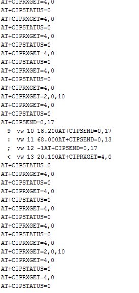
I doubt very much whether you, or anyone else, will enjoy using this code for very long.

As I’ve said multiple times in this topic, you can’t send debug data and AT commands for the SIM900 to the same pins and expect the Blynk connection to work consistently.
What you are doing is the equivalent of trying to have four people having simultaneous conversations down a single phone line.

You need to turn off all debug serial prints, by deleting/commenting-out #define BLYNK_PRINT Serial, all Serial.print statements, and the Serial.begin(115200) commands.
This will mean that you are ‘flying blind’, without any means of debugging your code or connection status via the serial monitor, but this is the only way of achieving the results you require with this many peripherals connected to a NodeMCU board.

By far the simplest solution to this is to use an ESP32 board, preferably one with a built-in GPRS modem such as the TTGO T-CALL, but an ESP32 dev board with an external SIM800/900 would work just as well.

Pete.

I’m well aware that what I did was more a hack than an elegant per book solution HOWEVER it works for me the way it is.

What you are doing is the equivalent of trying to have four people having simultaneous conversations down a single phone line.

I agree on this one HOWEVER:
1/ except for the lamp/pump on messages the original code wasn’t sending much on the serial monitor if at all so one person is off the conversation
2/ after I disabled the notifications that’s another person off
3/ the code is already debugged for my needs but even if some debugging was necessary one can always revert to the original WiFi code and do whatever needs to be done
4/ that leaves only one person in the conversation talking to the SIM900 module.
I also have the option to loose the buttons (which I don’t really need) and implement software serial so it will work one way or another.
Some interruptions are not critical for this application at all. Whether I’m going to get data every 10 seconds or every 5 minutes doesn’t really matter because in agriculture processes are not affected by such short periods of time. Moreover I need this for hobby not industrial purposes.

Now that I know the limitations of my current setup next time (if at all) I’ll get an ESP32 board or the TTGO module.