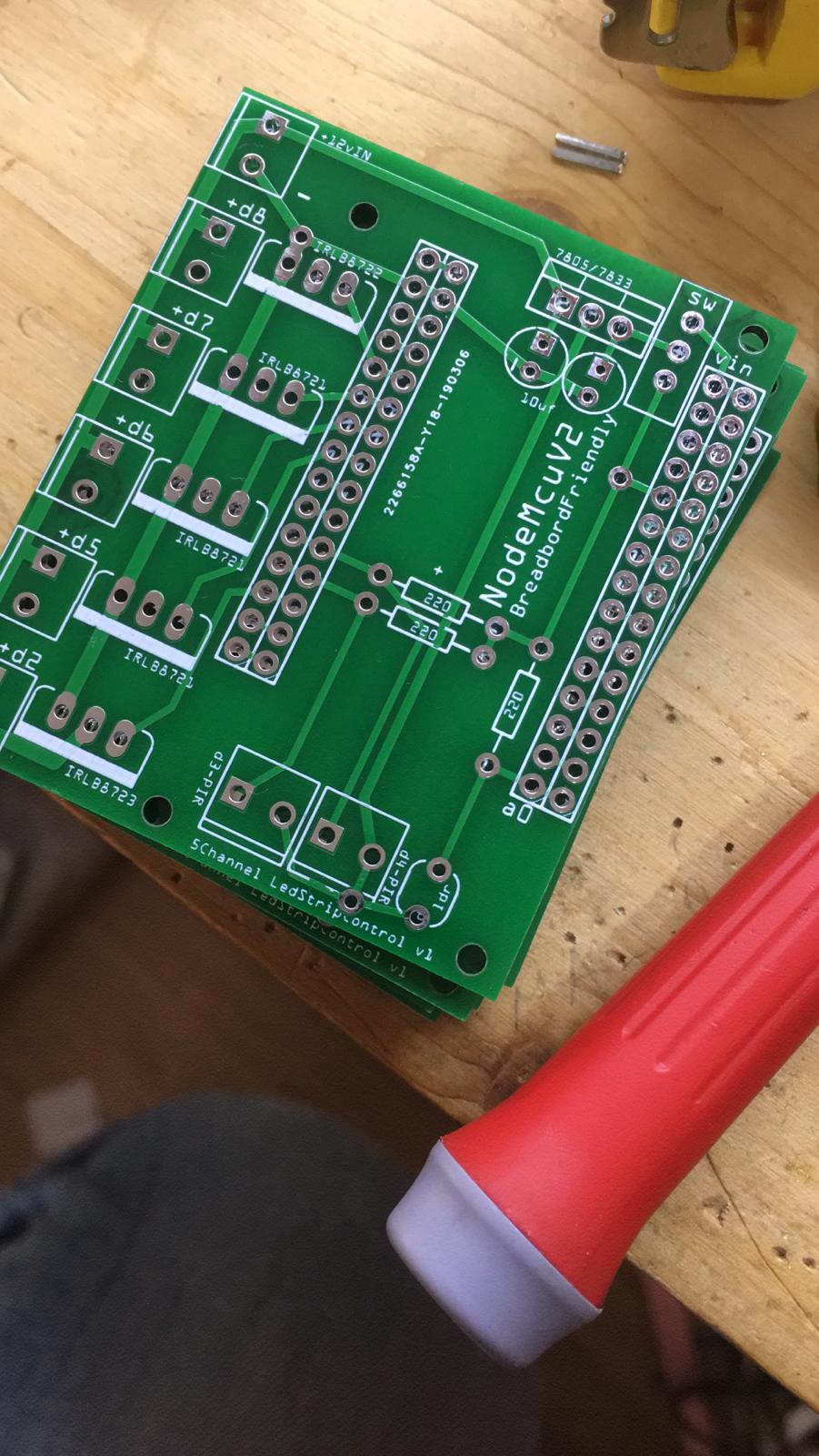
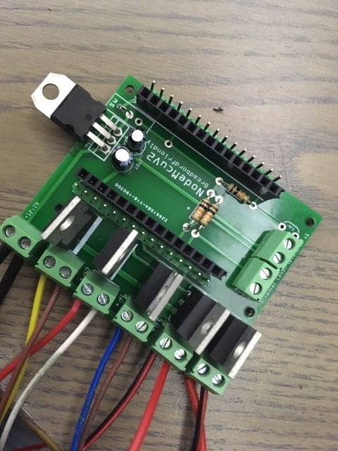
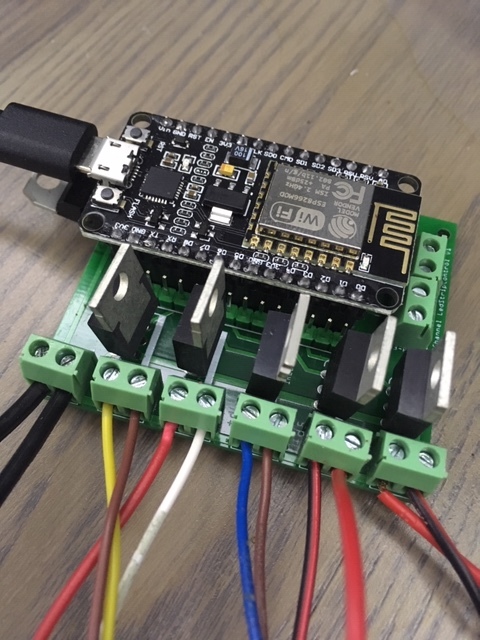
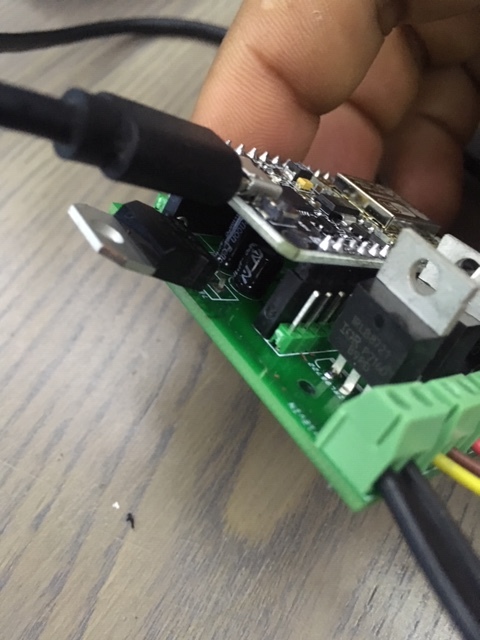
Hello there. I want to share my project with you. I designed a 5 channel led strip control circuit. You can control LEDs with external sensors that you connect to this circuit. If you are installing a motion sensor, I recommend that you do not use the ones developed for arduino. Use the ones developed for the alarm system. They work a lot more smoothly and stable. In addition, these sensors work with 12v such as Led Strip, you do not experience voltage problems. You can control the 5-meter Led Strip with each channel. If you want it to look as clean as I do, I’ll share the files below to make the PCB.
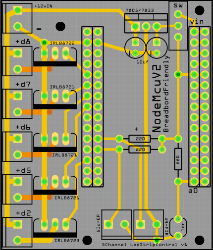
You can use a 7805 or 7833 voltage regulator. Whichever you use, you must select the appropriate jumper on the side according to the voltage regulator.
Parts:
1x NodeMcu V2 (Breadbord Friendly Model) : Link
4x IRLB8721 : Link
5x 2pin connector : Link
1x Femail Header(1x15p) : Link
1x Male Header : Link
Optional Part(s):
2x PIR Sensor : Link
1x LDR Sensor
PCB File : Link
Library : Link
Code
#define BLYNK_PRINT Serial
#include <ESP8266WiFi.h>
#include <BlynkSimpleEsp8266.h>
#include <FadeLed.h>

char auth[] = "xxx";
char ssid[] = "NtgAdmin";
char pass[] = "xxx";
//char server[] = "192.168.1.2";  // IP for Local Cloud Server
char server[] = "localServerAddress";  // URL for Blynk Cloud Server
int port = 8080;
bool isFirstConnect = true;

unsigned long previousMillis = 0; // last time update
unsigned long currentMillis = 0;
long interval = 7000; // interval at which to do something (milliseconds)
bool sensor1Actived = false;
bool sensor2Actived = false;

FadeLed ledD2(D2);
FadeLed ledD5(D5);
FadeLed ledD6(D6);
FadeLed ledD7(D7);
FadeLed ledD8(D8);
int button1 = D3; //pir sensor1
int buttonState1 = 0;
int button2 = D4; //pir sensor2
int buttonState2 = 0;

int  ledD2Time = 300;
int  ledD5Time = 300;
int  ledD6Time = 300;
int  ledD7Time = 300;
int  ledD8Time = 300;

void setup() {
  // put your setup code here, to run once:
  Serial.begin(9600);
  WiFi.begin(ssid, pass);  // Non-blocking if no WiFi available
  Blynk.config(auth, server, port);
  Blynk.connect();
  pinMode(button1, INPUT);
  pinMode(button2, INPUT);

  FadeLed::setInterval(15);
  ledD2.setTime(ledD2Time, true);
  ledD5.setTime(ledD5Time, true);
  ledD6.setTime(ledD6Time, true);
  ledD7.setTime(ledD7Time, true);
  ledD8.setTime(ledD8Time, true);
}


BLYNK_CONNECTED() {
  Serial.println("Connected");
  if (isFirstConnect) {
    Blynk.syncAll();
    isFirstConnect = false;
  }
}

void loop() {
  FadeLed::update();
  Blynk.run();
  currentMillis = millis();
  // put your main code here, to run repeatedly:
  buttonState1 = digitalRead(button1);
  buttonState2 = digitalRead(button2);
  //Serial.print(buttonState1);
  //Serial.print("          ");
  //Serial.println(buttonState2);

  if (buttonState1 == LOW) {
    previousMillis = currentMillis;
    sensor1Actived = true;
  }


  if (buttonState2 == LOW) {
    previousMillis = currentMillis;
    sensor2Actived = true;
  }

  if (sensor1Actived == true) {
    ledD2.on();
    if (ledD2.done()) {
      ledD5.on();
      if (ledD5.done()) {
        ledD6.on();
        if (ledD6.done()) {
          ledD7.on();
          if (ledD7.done()) {
            ledD8.on();
          }
        }
      }
    }
  }

  if (sensor2Actived == true) {
    ledD8.on();
    if (ledD8.done()) {
      ledD7.on();
      if (ledD7.done()) {
        ledD6.on();
        if (ledD6.done()) {
          ledD5.on();
          if (ledD5.done()) {
            ledD2.on();
          }
        }
      }
    }
  }


  if (currentMillis - previousMillis >= interval)   {
    previousMillis = currentMillis;
    //ledD2.falling();
    ledD2.off();
    ledD5.off();
    ledD6.off();
    ledD7.off();
    ledD8.off();
    sensor1Actived = false;
    sensor2Actived = false;
  }
}
I have designed the code with the PIR sensor activated and flashing with the fade effect. What you do with Blynk is up to your imagination. You can also control manually via Blynk
It’s not an unusual project, but I hope it helps someone who needs it.