Kev, I think he wants you to pop round to his house and install it for him, you can do that - right?
Pete.
Kev, I think he wants you to pop round to his house and install it for him, you can do that - right?
Pete.
haha!!! Pete, of course I could !!!
Only one problem - last time I looked, Indonesia was outside Yorkshire…
Pete.
Kamu Terlalu Congkak
One day you will be made aware of God, and do not consider other people stupid, let alone bring the name of the country
Does God have anything to do with Blynk ? 
I’m not sure @PeteKnight will help you with your blynk project, no-one else.
Maybe God ? 
I read this project a long time ago & I found subjects that may facilitate the DIY.
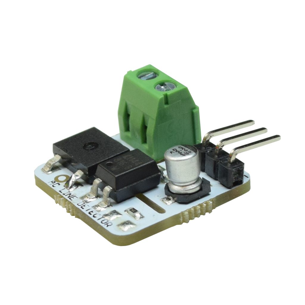
I saw in your hardware set-up picture.
Where did you installed the AC 220V 8 Channel Optocoupler Isolation Voltage Test Board MCU TTL for PLC |… I saw only relays and Arduino borad in your hardware set-up photo…
If you read back through the text you will see I usede 5v switching eliminating the need for the ac optocoupler board
hello @newdos your project are great. actually there is something i want to ask you about your project. can i change arduino R2 with nodemcu ESP 32. ive tried it with nodemcu ESP 32 and i change a bit the programing to ESP32 programing but when i try to verify it the arduino ide said ERROR COMPILING FOR BOARD ESP 32 DEV MODULE. so i wonder does it suitable to use ESP32 for this project and how to interface optocoupler isolation voltage test board with nodemcu ESP32? i hope you can help me and reply me as soon as possible.
cheers
Sorry I am not familiar with these boards that much - I’m sure it could work but pins would need reprogramming etc
Cheers
kev
Can you help me out?
I want to control 4 light bulbs with blynk and with 4 manual switches which are connected to nodemcu (i don’t want to use current sensor just like you). So for this purpose i think, i don’t need arduino uno. Nodemcu will be enough. Can you please give me the code for the above requirement with appropriate feedback mechanism? Just like in your code where switches are connected to 5v. I am new to programming so i am unable to write my own code. Please help me! I will be thankful!
And i want to use it on wifi and not on ethernet.
And there is a code on 116th no. i think which serves my purpose but it has got some errors. Can you please fix them?
Hi Sanjay
The code listed earlier fully works as it is my current live code.
Various reprogramming would need top take place for the board you are using. have a go at simplifying the code for one lighting circuit and then just expand it. Thats how you learn!!
Thanks for the quick response. I will try.
Hello newdos,
I went shesd some time ago and bought 2 of those voltage sensing boards. I am however unable to detect reliable trigger input signals from them to s raspberry pi input gpio. Have you experienced an signal fluctuations that may be giving false readings? I remembered you doing something to adjust your time in your code end .my project is trying to do the same detecting of 110v AC for me to use my existing light switches and relay from a remote location being triggered via rpi and using hassio as the input detection of state changes with node red as the controller and automations .any assistance is greatly appreciated and thanks in advance
Hi, Never had any issue with these but only difference I was using UK 240v AC perhaps the 110 may be an issue ???