hey blynkers, i get this message on my serial monitor when I start the Blynkedgent program.
the program works fine but keep getting this readout every 1 sec on my serial monitor. i did hold reset for 10 sec. but still happens…
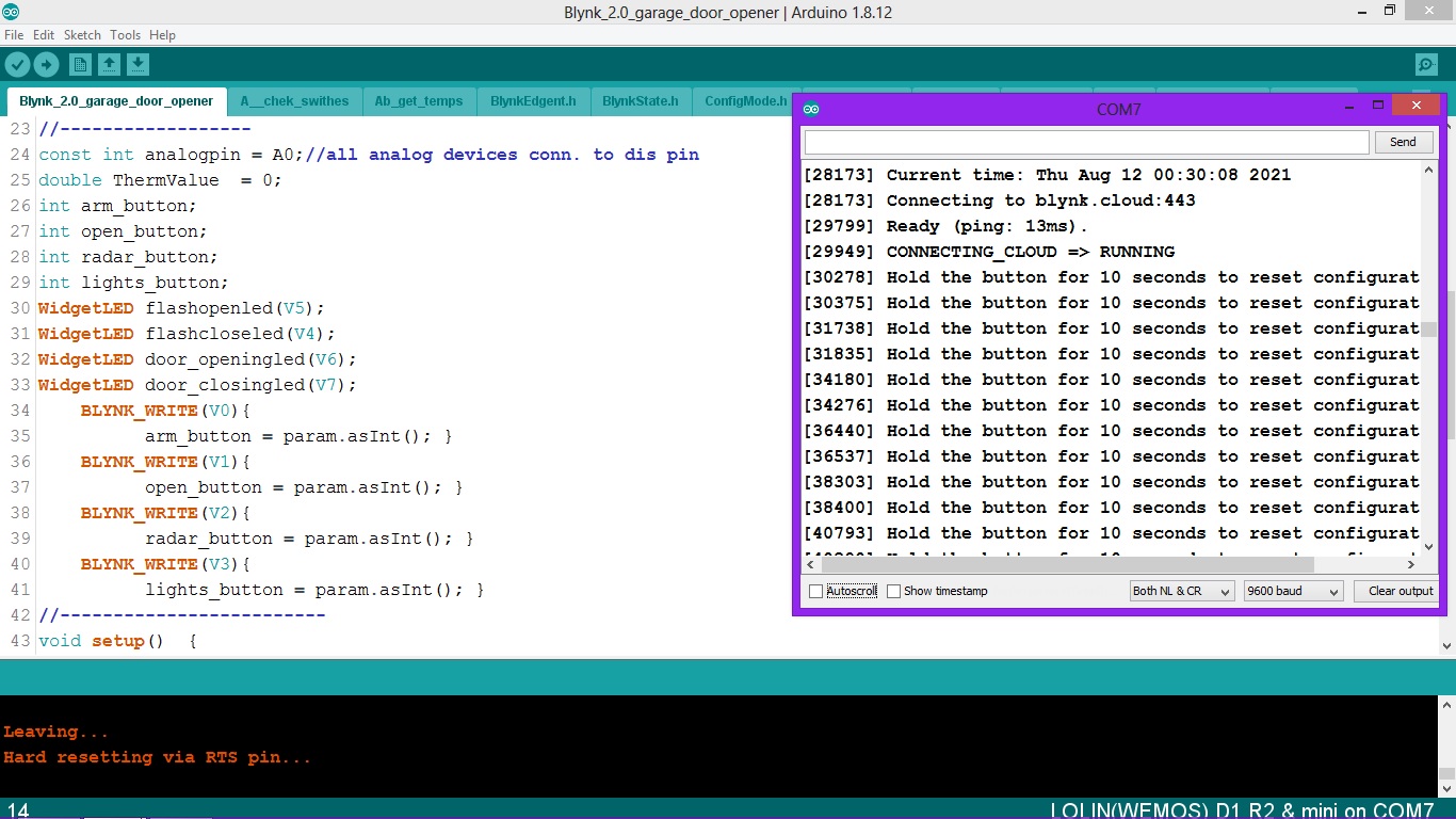
Blynk edgent is waiting for you to provide your SSID and your password ? 
Connect with your phone you will see the home page.
Difficult to say unless you post your sketch, and provide details of the board you are using and what configuration you have in your Settings.h file.
Pete
It seems you are using the reset pin for something else in your project. The reset pin they are referring to is not the reset pin on the board. If I remember correctly D8 is used as the reset pin.
It seems like gpio0 is on D3 on the “D1 R2” boards.
ok I will try to post my sketch ? I have never done this ? how may I ask do you post your sketch ?
yes and I am using the wemos D1 mini and I am using gpio15 and 16 in my sketch , maybe this is not going to work…
You put triple backticks on a blank line above and below the code.
Triple backticks look like this:
```
Copy and paste them if necessary.
Pete.
thanks pete here is me code
#define BLYNK_TEMPLATE_ID "TMPLZE-3D_x-"
#define BLYNK_DEVICE_NAME "Garage door opener"
#include <SimpleTimer.h>
#define BLYNK_FIRMWARE_VERSION        "0.1.0"
#define BLYNK_PRINT Serial
//#define APP_DEBUG
#define USE_WEMOS_D1_MINI
#include "BlynkEdgent.h"
#include <math.h>
#include <OneWire.h>
#include <DallasTemperature.h>
BlynkTimer timer;
#define ONE_WIRE_BUS 0  // this is D3 on wemos mini
OneWire oneWire(ONE_WIRE_BUS);
DallasTemperature sensors(&oneWire);
DeviceAddress atticprobe1 = {  0x28, 0xFF, 0xF4, 0x7E, 0xA4, 0x16, 0x04, 0x03 };
//------------------
int openswitch = 1;
int switchState = 1;       // used for door sw programs
int lastSwitchState = 1;
int lastopensw = 1;
//------------------
const int analogpin = A0;//all analog devices conn. to dis pin
double ThermValue  = 0;
int arm_button;
int open_button;
int radar_button;
int lights_button;
WidgetLED flashopenled(V5);
WidgetLED flashcloseled(V4);
WidgetLED door_openingled(V6);
WidgetLED door_closingled(V7);
    BLYNK_WRITE(V0){
          arm_button = param.asInt(); }
    BLYNK_WRITE(V1){
          open_button = param.asInt(); }
    BLYNK_WRITE(V2){
          radar_button = param.asInt(); }
    BLYNK_WRITE(V3){
          lights_button = param.asInt(); }
//-------------------------
void setup()  {
      Serial.begin(9600);
      delay(100);
      BlynkEdgent.begin();
      pinMode(14, INPUT_PULLUP);//door closed sw, pin D5 on wemos mini/active low
      pinMode(16, INPUT_PULLUP);//door open sw,  pin D0 on wemos mini /active low
      pinMode(5, OUTPUT);//activate for temp(4066), D1 on wemos mini
      pinMode(4, OUTPUT); //activate for power supply voltage on arduino(4066), D2 on wemos mini
      pinMode(12, OUTPUT);// ARM transistor, D6 on wemos mini
      pinMode(13, OUTPUT);// momentary open/close transistor, D7 on wemos mini
      pinMode(15, OUTPUT);//radar transistor
      pinMode(2, OUTPUT);//lights
      digitalWrite(13, LOW);
      digitalWrite(12, LOW);
      digitalWrite(5, LOW);
      digitalWrite(4, LOW);
      digitalWrite(15, LOW);
      digitalWrite(2, LOW);
      sensors.begin();
      sensors.setResolution(atticprobe1,9);
      timer.setInterval(2301L,getTemperature);
      timer.setInterval(450L,check_switches);
   }
//--------------------------
void loop() {
      BlynkEdgent.run();
      timer.run();
   }
//-------------------------
/*
 * Board configuration (see examples below).
 */

#if defined(USE_NODE_MCU_BOARD) || defined(USE_WEMOS_D1_MINI)

  #define BOARD_BUTTON_PIN            0
  #define BOARD_BUTTON_ACTIVE_LOW     true

 // #define BOARD_LED_PIN               2
 // #define BOARD_LED_INVERSE           true
 // #define BOARD_LED_BRIGHTNESS        255

#elif defined(USE_SPARKFUN_BLYNK_BOARD)

  #define BOARD_BUTTON_PIN            0
  #define BOARD_BUTTON_ACTIVE_LOW     true

  #define BOARD_LED_PIN_WS2812        4
  #define BOARD_LED_BRIGHTNESS        64

#elif defined(USE_WITTY_CLOUD_BOARD)

  #define BOARD_BUTTON_PIN            4
  #define BOARD_BUTTON_ACTIVE_LOW     true

  #define BOARD_LED_PIN_R             15
  #define BOARD_LED_PIN_G             12
  #define BOARD_LED_PIN_B             13
  #define BOARD_LED_INVERSE           false
  #define BOARD_LED_BRIGHTNESS        64

#else

  #warning "Custom board configuration is used"

  #define BOARD_BUTTON_PIN            0                     // Pin where user button is attached
  #define BOARD_BUTTON_ACTIVE_LOW     true                  // true if button is "active-low"

    #define BOARD_LED_PIN               4                     // Set LED pin - if you have a single-color LED attached
  //#define BOARD_LED_PIN_R           15                    // Set R,G,B pins - if your LED is PWM RGB
  //#define BOARD_LED_PIN_G           12
  //#define BOARD_LED_PIN_B           13
  //#define BOARD_LED_PIN_WS2812      4                     // Set if your LED is WS2812 RGB
  #define BOARD_LED_INVERSE           false                 // true if LED is common anode, false if common cathode
  #define BOARD_LED_BRIGHTNESS        64                    // 0..255 brightness control

#endif


/*
 * Advanced options
 */

#define BUTTON_HOLD_TIME_INDICATION   3000
#define BUTTON_HOLD_TIME_ACTION       10000

#define BOARD_PWM_MAX                 1023

#define CONFIG_AP_URL                 "blynk.setup"
#define CONFIG_DEFAULT_SERVER         "blynk.cloud"
#define CONFIG_DEFAULT_PORT           443

#define WIFI_NET_CONNECT_TIMEOUT      30000
#define WIFI_CLOUD_CONNECT_TIMEOUT    60000
#define WIFI_AP_IP                    IPAddress(192, 168, 4, 1)
#define WIFI_AP_Subnet                IPAddress(255, 255, 255, 0)
//#define WIFI_CAPTIVE_PORTAL_ENABLE

#define USE_TICKER
//#define USE_TIMER_ONE
//#define USE_TIMER_THREE
//#define USE_TIMER_FIVE
//#define USE_PTHREAD

#define BLYNK_NO_DEFAULT_BANNER

#if defined(APP_DEBUG)
  #define DEBUG_PRINT(...) BLYNK_LOG1(__VA_ARGS__)
#else
  #define DEBUG_PRINT(...)
#endif
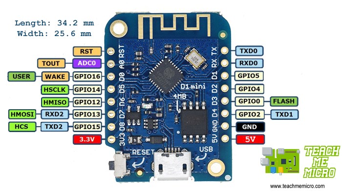
GPIO0 is being used as the button that you press for 10 seconds to reset the provisioning data, so should have a physical push switch connected to it, but you’re also using it for your one wire bus.
It seems like you’ve run out of GPIOs. Maybe time to use an ESP32 instead?
Pete.
1 Like
so I should leave D3 open and not used ?
As In said, D3 should have a push switch attached to it, but if you do that then you have nowhere to connect your Dallas temperature sensor.
Pete.
ok I see I might have to do some redesign , I just have a **** load of wemosD1 mini. maybe I will use the ESP32… thanks so much Pete , you da man… 
It depends on whether you want the Edgent functionality, and also whether you want everything connected to one board.
If you don’t want Edgent and Blynk.Air then use a simpler static provisioned sketch.
If you want to use multiple boards, maybe in different locations the use the HTTP(S) Bridge approach.
If you want everything then an ESP32 is the way forward.
Pete.
 you are absolutely right, by me using gpio 0 as temp sensor input caused all the trouble. all is good now.