First part of my heatpump project is finally done.
I have an “air to water” heatpump, and the only option to see status temperatures, is to press a button for actual temps and look at the powermeter counter, delivering power to the unit.
Primary goal
I wanted a more detailed day to day and hour to hour insight of temperatures and poweruse and to compare it with the outdoor temperature.
Want to monitor
- forward temperature flow to floor heating
- return temperature flow from floor heating
- hot water tank temperature.
- outdoor temperature
- realtime poweruse
- average poweruse pr hour
I have used alot from other projects and learned alot too on the way.
This one needs to be mentioned, duo to I have used alot of his code for the attiny85 and the powermeter part:
Items used in this
1x Arduino uno
1x W5100 ethernet shield
1x Prototype shiels for the arduino uno
3x DS18B20 digital temperature sensors
1x outdoor DS18B20 digital temperature sensor (waterproof)
1x attiny85 microcontroller
1x LDR sensor
4x 4.7k resistors
1x 2.2k resistor
1x 10uf capacitor (to program the attiny85)
wires (and soldering if fitting it on a prototype sheild)
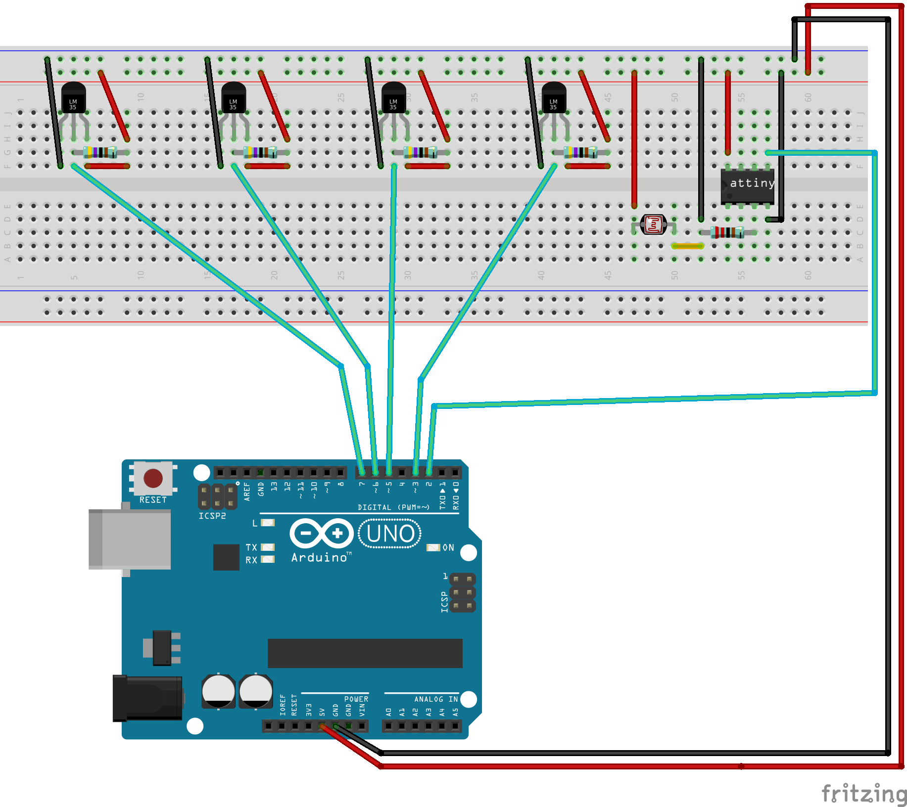
Hardware setup
Connect it as shown in the Fritzing drawing below.
One of the four temperature sensors can be replaced with an outdoor version.
In my project I didnt need to use a LDR sensor but the code is meant for one. And I was so lucky that my powermeter had a +/- output, which I used instead of the LDR sensor.
The code
First you need to program the attiny85.
The attiny85 is used to monitor the LDR in realtime and when input from the LDR it sends an output to the arduino.
Dont know if it could be done without the attiny85.
Using this guide will help you on whow to program the attiny85:
Remember to momentary program the arduino uno with the arduinoISP sketch, before programming the attiny85.
The arduinoISP sketch is a default sketch in the arduino IDE program.
The code for the attiny85
void setup()
{
  pinMode(0, OUTPUT); //pin 0 output
}

void loop()
{
  int FotoR = analogRead(3); //input pin 3 to LDR sensor
  {

    if (FotoR >= 100) // LDR sensibility
    {
      digitalWrite(0, HIGH); //
     delay (100);
    }
    else
    digitalWrite(0, LOW); //
  }

}
What it does, is reading input from pin3 and when result is higher than 100, it sets pin0 in high state.
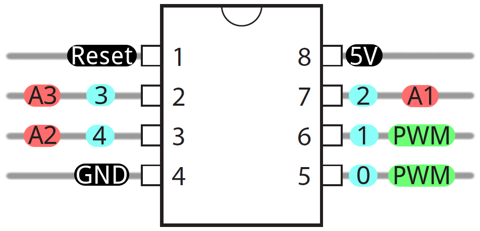
here is the layout of the attiny85 to better understand the pins.
The code for the arduino uno
#include <SimpleTimer.h>
#define BLYNK_PRINT Serial    // Comment this out to disable prints and save space
#include <SPI.h>
#include <Ethernet.h>
#include <BlynkSimpleEthernet.h>
#include <OneWire.h>
#include <DallasTemperature.h>

#define DEBUG


// Digital pin the DS18B20 is connected to. Do not use digital pins 0 or 1 since those conflict with the use of Serial.
const int tmpPin1 = 7;
const int tmpPin2 = 6;
const int tmpPin3 = 5;
const int tmpPin4 = 3;

// output from Attiny85
const byte interruptPin = 2;

OneWire oneWire1(tmpPin1);
OneWire oneWire2(tmpPin2);
OneWire oneWire3(tmpPin3);
OneWire oneWire4(tmpPin4);


DallasTemperature sensors1(&oneWire1);
DallasTemperature sensors2(&oneWire2);
DallasTemperature sensors3(&oneWire3);
DallasTemperature sensors4(&oneWire4);


SimpleTimer timer;
char auth[] = "xxxxxxx";


// powermeter
long pulseCount = 0;
long pulseCounthour = 0;
long powerhour = 0;

//Used to measure power.
unsigned long pulseTime, lastTime, elapsedTime;

//power and energy calculation
double power, elapsedkWh, elapsedkWh2, powerhouraverage;

//Number of pulses per wh - found or set on the meter.
int ppwh = 1; //1000 pulses/kwh = 1 pulse per wh


void setup()
{
  Serial.begin(9600);
  Blynk.begin(auth);

  // kWh interrupt attached to gpio2 and pin0 on attiny85 (leg5)
  attachInterrupt(digitalPinToInterrupt(interruptPin), onPulse, FALLING);

 while (Blynk.connect() == false)
    {
    // Wait until connected
    }


  // These timers are used so data does not flood Blynk
  timer.setInterval(3003L, sendSensor1);
  timer.setInterval(3006L, sendSensor2);
  timer.setInterval(3009L, sendSensor3);
  timer.setInterval(3012L, sendSensor4);
  timer.setInterval(3016L, sendUptime);
  timer.setInterval(3600000L, resetvalues); //interval timer for average time kWh is calculated and plotted to graph.
}


void loop()
{
  Blynk.run();
  timer.run();

}


// You can send any value at any time.
// Please don't send more that 10 values per second.

void sendSensor1()
{
  sensors1.requestTemperatures();
  Blynk.virtualWrite(1, sensors1.getTempCByIndex(0) + 6.5); //adjusted with 6.5 celsius because measuring outside of tube
}

void sendSensor2()
{
  sensors2.requestTemperatures();
  Blynk.virtualWrite(2, sensors2.getTempCByIndex(0) + 6.5); //adjusted with 6.5 celsius because measuring outside of tube
}

void sendSensor3()
{
  sensors3.requestTemperatures();
  Blynk.virtualWrite(3, sensors3.getTempCByIndex(0) + 6.5); //adjusted with 6.5 celsius because measuring outside of tube
}

void sendSensor4()
{
  sensors4.requestTemperatures();
  Blynk.virtualWrite(10, sensors4.getTempCByIndex(0));
}

// sending power measuring to blynk
void sendUptime()
{
  Blynk.virtualWrite(4, power); // pin virtual
  Blynk.virtualWrite(5, elapsedkWh); // pin virtual
  Blynk.virtualWrite(6, powerhouraverage); // pin virtual

}

// The interrupt routine when receiving pulse from attiny85 which is connected to LDR
void onPulse()
{

  //used to measure time between pulses.
  lastTime = pulseTime;
  pulseTime = millis();

  //pulseCounter
  pulseCount++;
  pulseCounthour++;

  //Calculate power
  power = (36000000 / (pulseTime - lastTime))*(ppwh*0.01);
  powerhour = powerhour + power;


  // just for control calculation
  elapsedTime = (pulseTime - lastTime);

  //Find kwh elapsed
  elapsedkWh = (1.0*pulseCount/(ppwh*100)); //multiply by 1000 to pulses per wh to kwh convert wh to kwh


  //Testing values for serialprint
    //Serial.print("Power pr kwh between pulses : ");
    //Serial.print(power);
    //Serial.print("\npulseTime: ");
    //Serial.print(pulseTime);
    //Serial.print("\nlastTime: ");
    //Serial.print(lastTime);
    //Serial.print("\nelapsedTime: ");
    //Serial.print(elapsedTime);
    //Serial.print("\nelapsedkwh: ");
    //Serial.print(elapsedkWh);
    //Serial.print("\nsending power result\n\n");


}


void resetvalues()
{
  //calculates kWh for defined time set in simple.timer "resetvalues"
  //gives better average when settingtime to +15min/9000000ms

  powerhouraverage = powerhour / pulseCounthour;

  // resets variables after the have been sent to Blynk (in sendUptime)
  powerhour = 0;
  pulseCounthour = 0;


}
Comments to the code
The temperature part
It’s quite forward, though I have added 6.5 celsius to some of the readings because I’m measuring on the outside of some copper tubes. And I found out that 6.5 celsius is mostly the difference from measuring outside and inside those tubes.
The powermeter part
Most of it is from the orignal author, but I have converted it to arduino uno, and changed some and added other parts.
I have left alot of comments from the original code, but also added some of mine.
One of the changes in the powermeter part, is that my powermeter outputs 100 blinks pr kWh and not 1000 blinks.
I have also added some testing calculations and serialprints to test with.
And I have added a more “wide average calculation” to get a better and more realistic result meassured over time, instead of only meassuring between current and last pulse.
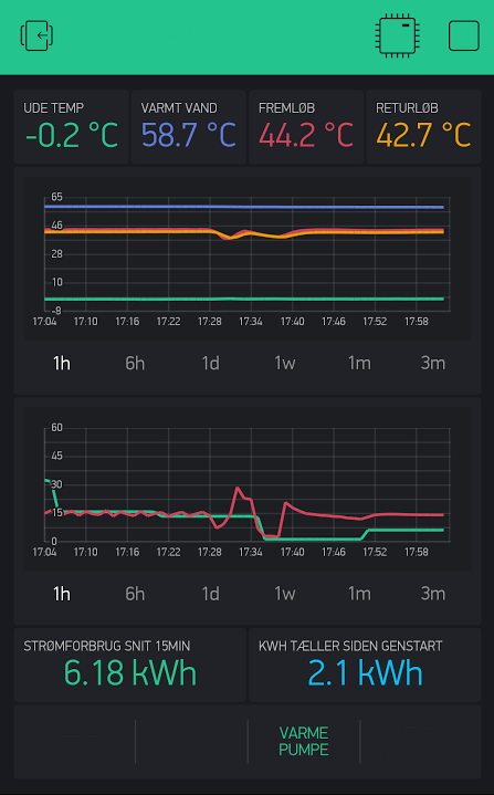
Explanation of the Blynk setup
Sorry but the labels are in danish
From top left:
Outdoor temp V10, Hotwater V3, Forward temp V2, Return temp V1
The first history graph shows all temps compared.
The second history graph shows
In red, realtime poweruse (V4)
In green, calculated average poweruse in 15min interval (V6).
From bottom left:
calculated average poweruse V6
kWh counter from last restart V5.
I hope it all makes sense, or else ask and I will try to elaborate.
By the way, I’m still testing the calculated average poweruse, maybe 15 minutes is too short a time to measure in.
Edit: Updated the code to 1 hour calculated average poweruse.
Thomas