Robot with Esp8266 Shield and Arduino Nano

Hi friends,
I’d like to share with you this little project using Blynk and Local Server.
I have been enjoying a lot doing it. Thanks for this huge program called Blynk!!!

Please, keep in mind I’m just a beginner… the code is NOT perfect but it works!

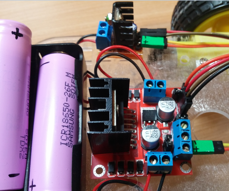
I have been playing with a Dual H Bridge Stepper Motor Drive Controller Board and two DC Gear Motors.

The power supply is just two Li-ion Batteries 3.7V (7.4V to power the DC motors).
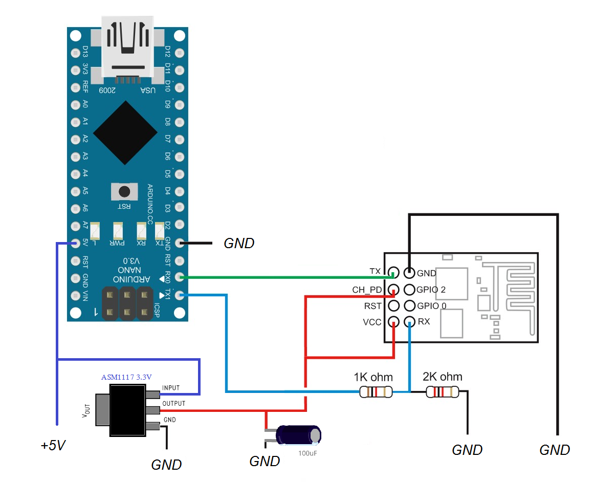
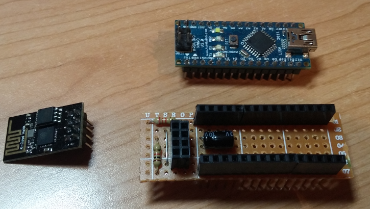
There’s a LM7805 to feed the Arduino and a small ASM1117 3.3V for the ESP8266.

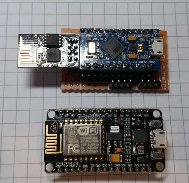
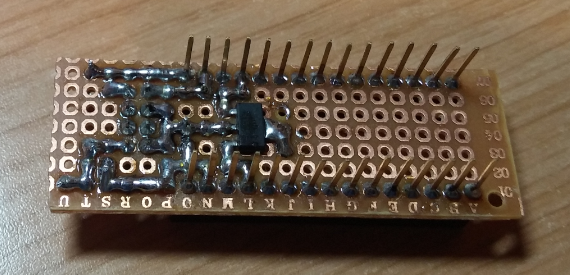
I have done a small Shield with a piece of a PCB Board to join the ESP8266 and the Arduino Nano. (I’m really happy with this shield, It works really well)

You can see below my code:

//#define BLYNK_DEBUG
//#define BLYNK_PRINT Serial    // Comment this out to disable prints and save space
#include <ESP8266_HardSer.h>
#include <BlynkSimpleShieldEsp8266_HardSer.h>

// Set ESP8266 Serial object
#define EspSerial Serial
ESP8266 wifi(EspSerial);


int motorA ;
int motorB ;
int X=0;
int Y=0;
int factor=0;
int maximo=70;

// You should get Auth Token in the Blynk App.
// Go to the Project Settings (nut icon).
char auth[] = "xxxxxxxxxxxxxxxxxxxxxxxxxxx";

void setup()
{
  // Set console baud rate
  Serial.begin(9600);
  delay(10);
  // Set ESP8266 baud rate
  EspSerial.begin(9600);
  delay(10);

 Blynk.begin(auth, wifi,"xxxxxxx","xxxxxxxxxxxxx","xxx.xxx.x.xx");

 pinMode(motorA, OUTPUT); 
 pinMode(motorB, OUTPUT);

}

 BLYNK_WRITE(V1) 
{
 int X1 = param.asInt();
 X=X1;
}

 BLYNK_WRITE(V2)
{
 int Y1 = param.asInt();
 Y=Y1;
}

 BLYNK_WRITE(V0)//      slider  de 100 a 255!!!!
{
 int vel = param.asInt(); 
 maximo=vel;
}

void loop()
{

  if(X == 128  &&  Y == 128)  //  Parados OK
  {
   motorA = 0;
   motorB = 0;
   analogWrite(5, motorA);  
   analogWrite(6, motorA);
   analogWrite(10, motorB);  
   analogWrite(9, motorB);
   } 
   
   if(X >= 129 && Y == 128)   //Avance OK
  {
    motorA = X;
    motorB = X;
    
    motorA = map(motorA, 129,255 , 70,maximo);
    analogWrite(5, motorA);
    analogWrite(6,0);
    motorB = map(motorB, 129,255 , 70,maximo);
    analogWrite(10, motorB);
    analogWrite(9,0);
  }
   if(X >= 129 && Y <= 127)   //Avance Derecha OK
  {
    motorA = X;
    motorB = X;
    factor = Y;
    factor= map(factor,0,127,35,0);
    
    motorA = map(motorA, 129,255 , 70,maximo);
    analogWrite(5, motorA);
    analogWrite(6,0);
    motorB = map(motorB, 129,255 , 70,maximo);
    analogWrite(10, (motorB-factor));
    analogWrite(9,0);
  }
   if(X >= 129 && Y >= 129)   //Avance Izquierda OK
  {
    motorA = X;
    motorB = X;
    factor = Y;
    factor= map(factor,129,255, 0,35);
    
    motorA = map(motorA, 129,255 , 70,maximo);
    analogWrite(5, (motorA-factor));
    analogWrite(6,0);
    motorB = map(motorB, 129,255 , 70,maximo);
    analogWrite(10, motorB);
    analogWrite(9,0);
  }
  if(X <= 127 && Y ==128)   //Retroceso OK
  {
    motorA = X;
    motorB = X;
    
    motorA = map(motorA, 0,126 , maximo,70);
    analogWrite(6, motorA);
    analogWrite(5,0);
    motorB = map(motorB, 0,126 , maximo,70);
    analogWrite(9, motorB);
    analogWrite(10,0);
  }
  if(X <= 127 && Y <=127)   //Retroceso Derecha OK
  {
    motorA = X;
    motorB = X;
    factor = Y;
    factor= map(factor,0,127, 35,0);
    
    motorA = map(motorA, 0,126 , maximo,70);
    analogWrite(6, motorA);
    analogWrite(5,0);
    motorB = map(motorB, 0,126 , maximo,70);
    analogWrite(9, (motorB-factor));
    analogWrite(10,0);
  }
  if(X <= 127 && Y >=129)   //Retroceso Izquierda OK
  {
    motorA = X;
    motorB = X;
    factor = Y;
    factor= map(factor,129,255, 0,35);
    
    motorA = map(motorA, 0,126 , maximo,70);
    analogWrite(6, (motorA-factor));
    analogWrite(5,0);
    motorB = map(motorB, 0,126 , maximo,70);
    analogWrite(9, motorB);
    analogWrite(10,0);
  }
  
  Blynk.run();
}

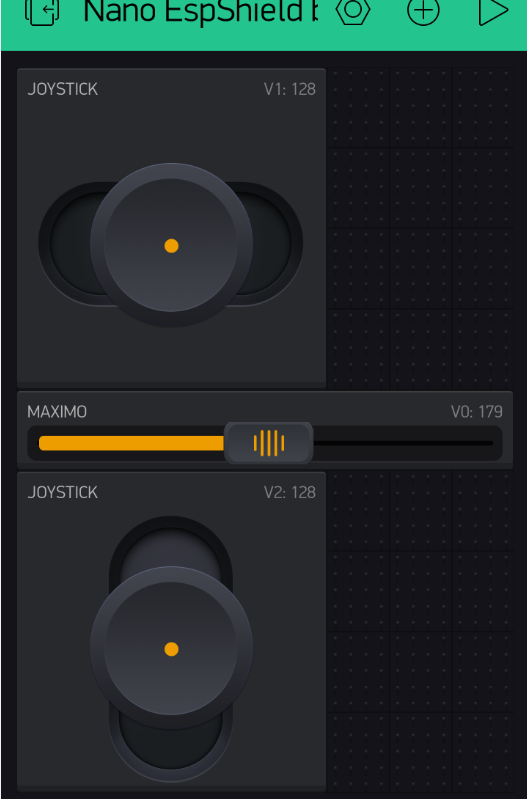
The code itself is really simple, using 2 Joysticks and a Large Slider I can control the movement forward, backward and turn on the left and right.
I use the Slider to fix the speed (the Slider works between 100 and 255) This way my daugther can play with the robot easily.
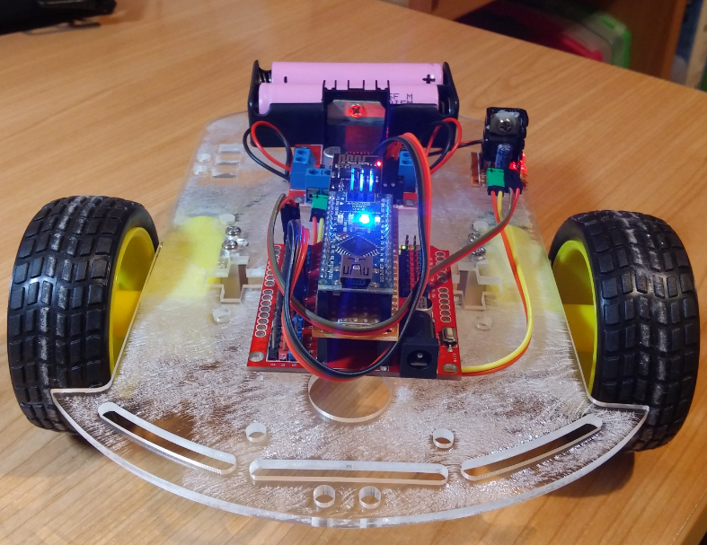
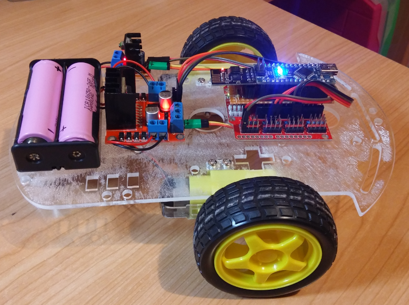
And some photos:

You can see the video here:

I’m using a Tablet with “Shared Access”.
I hope you like it!!!

Kind regards

10 Likes

That, my friend, freaking awesome! Also a very nice way to get more girls involved with technology!

So simple, but effective. I love it!

3 Likes

Also a very nice way to get more girls involved with technology!

:laughing:

1 Like

Unfortunately it’s a fact of life, we need more women involved in technology to keep up with everybody. My wife usually has great ideas, just not the means to execute them from a technological point of view. It’s a waste to let that all go to waste, sort of speak :wink:

2 Likes

Lichtsignaal,thanks for your comments, she loves my “gadgets” and I enjoy showing her what I do just for fun.

Kind regards!

1 Like

Thanks for sharing, Jose. I posted it on our FB page and will do the same on Twitter! I’m amazed how fast the communication between tha app and robot is.

4 Likes

Nice project psoro.

I’m working with Nano’s but just USB Serial at present. Can you please direct me to a decent set up guide for the pinout on the small shield you made and a good source for the Esp8266’s.

2 Likes

Hi Costas,
The small Shield is based on the next set up:

The small ASM1117 is good enough to feed the ESP8266

I hope it helps. :smile:

2 Likes

Thanks for the schematic psoro. I will work through it as soon as possible.

1 Like

psoro is it not possible to take the 3.3V feed from the Nano pin for the ESP8266?

Yes, you can do that, but the ESP needs more power then the Nano can deliver. If you take power from the Nano you possibly blow up your Nano.

Thanks Lichtsignaal. I have about 30 off CH340G USB to TTL adapters with pins for 3.3V and 5V.
I believe the ESP8266 needs around 300mA but 500mA supply is recommended. Do you think I would be OK taking a USB 2.0 (500mA) feed (at 3.3V) through the CH340G’s for the ESP’s?

I’m not sure. I’ve done similar things but I’d highly recommend a separate powersupply. My local Blynk projects seem to run way more stable with those. You can get really cheap adjustable dc-dc convertors or get 1A 5v powersupplies combines with pre-made 5v to 3.3v modules which are really timy and cheap (check ebay).

As I don’t know one end of a soldering iron from the other I think I might buy complete modules. Any recommendations for small (project cases already received), reliable and cheap?

These are the ones I got from Ebay. They even appear to work with voltages as high as 8v input without blowing up.

1 Like

I was looking at the same a couple of hours ago (2 for a dollar incl delivery).

Also read about USB to TTL which states ok for rx / tx but not power (as you said).

I might have tracked down the module I need, subject to price negotiation.

1 Like

This is exactly what I have been searching for. I am using the nodemcu in stand alone mode, but I believe your code will work. I can then start working on the differential steering some more. I am programming using the Arduino IDE so the coding is going to be pretty much the same I think. By the way im using these batteries: Digital Energy

NodeMCU for $7-10 and theMotor-Shield is $5-$7.

Hi MakerD!
I wanted to use the Nodemcu as you but my Windows 7 (64 bits) doesn’t like it… I wasn’t able to install properly the drivers for CP2102 (It’s a pitty…) that’s why I did this little shield.

Now I’ve done other little board to play with an Arduino Pro Micro and Blynk, the size compared to the Nodemcu is really similar:

4 Likes

Thats interesting. I have done it both ways at this point. The CP2102 is only for you to make the ESP8266 communicate with the usb on your computer. It is already built into the NodeMCU so you wouldn’t need it. Basically, you are using the Arduino in place of the CP2102 to configure the ESP8266 and then program the Arduino to pass and receive serial commands through the RX/TX connection. The NodeMCU can be used in the same way, but you can also add libraries to Arduino IDE and program the ESP8266 directly like you would the Arduino, cutting down your project cost and simplifying your circuit depending on your specific goal at the time. I think there are definitely situations where you want both to take advantage of different strengths of each board.

By the way, I am using Windows 10. You may want to look into it. It is a lot more maker friendly since Microsoft is looking to incorporate support for Arduino IDE support into their platform moving forward.