I don’t know where you obtained this sketch, but it’s a mess.
Some of the issues are…
You’re defining a SoftwareSerial port called EspSerial, but you’re using the Uno’s hardware serial pins to do this.
The baud rate for the SoftwareSerial port used to communicate with the ESP-01 can’t use a baud rare faster than 9600 because that’s the maximum that the Uno is capable of using when emulating a serial port - because of the Uno’s poor processor speed.
This baud rate also needs to match that of the ESP-01.
You are initialising the same Serial1 port (the hardware serial port of the Uno) twice.
blynk-cloud.com is the url for the old Legacy servers, which were decommissioned over a year ago.
This simple project was earlier working with legacy application. But now it was not working. so,I had gone thru all the posts and prepared this sketch. I was not able to ping blynk-cloud.com, that’s when i had doubt finally post here. As you suggested will go thru the post and correct myself
Serial.write(auth) -its nothing I was just testing
yes as suggested pin 2 from uno to Tx of ESP-01 and pin 3 from uno to RX of ESP-01.
How to configure ESP-01 baud rate. I am using new ESP-01
I did Ultrasonic Sensor module 6 years back, when i purchased, that time I am not aware of availability of NodeMCU. I just purchased Arduiono Uno and ESP8266 and trying to build a module to control the lights. Also I am not using FTDI, please advice what i have to do to complete the module, I will follow the same.
The tutorial that I linked to provides as much information as I’m prepared to commit to when it comes to configuring the ESP-01 module. This is simply because there are many different versions of the ESP-01 and ESP-01S AT firmware, and that’s assuming that the AT firmware hasn’t been overwritten by uploading a sketch to the ESP-01.
Also, there are many different versions of ESP-01 to USB adapter. Some are not fit for purpose, and others are quite good. There are also many varieties of standard FTDI adapters, but there is no standard pinout or standard way of switching to 3.3v output.
There are many tutorials on the internet about how to change the default baud rate on the ESP-01/S, so I’d study those.
Having said that, you’d be better spending money on a NodeMCU than on the hardware needed to change the default baud rate on your ESP-01.
No. But if you upload a sketch to the ESP-01 it will overwrite the factory AT firmware.
The ESP-01 will work, once you configure it correctly, but it takes more skill, knowledge and equipment than it does to use a NodeMCU to achieve the same results as the Uno + ESP-01 combo.
I have not uploaded anything to ESP-01/ESP8266. If I use NodeMCU, do I need to upload the sketch separately for NodeMCU. Also is NodeMCU is better option compared to ESP8266 . Before I could start using NodeMCU, I need some information.
As you suggested now i am using NodeMCU, its simple compared to Arduino UNO and esp8266. Now device is showing online in Dashboard, now no light is on in NodeMCU. only relay led is on indicating off. From blynk app if button is tured On/Off, nothing is working. From dashboard if clicked on Off, in blynk app also it turns off. But giveing message as Device is offline. Below is my sketch, please advise any changes is required.
You’ve told your sketch that your relay is connected to GPIO1, which is the pin labelled Tx, and is therefore not a good pin to use, as the Tx pin is use by the serial port and will interfere with debugging.
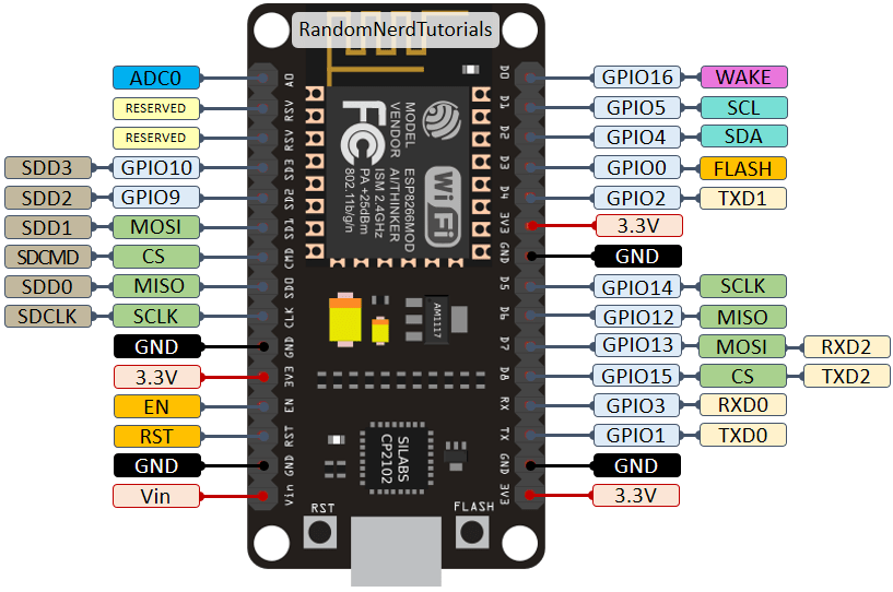
I’m guessing that you’re getting confused with the “D” numbers printed on the NodeMCU board, and you’ve connected your relay to the pin labeled D1, which is actually GPIO5…
That’s because you have no code in your sketch to turn the ModeMCU’s onboard LED on or off. The onboard LED is connected to GPIO2 (D4).
I don’t understand the rest of your comments, but you’d be better looking at your serial monitor to understand what’s happening with connections and disconnections.
More info on the NodeMCU and which pins to use here…