Hey!
I am a George 13yr old maker from INDIA, who wants your help in making a weather station with BLYNK app…
I am intending to make a weather station with Arduino Uno and esp8266 (ESP8266EX AI CLOUD) with blynk as Weather Moniter …I 've been searching past the weeks on tutorials regarding connecting esp8266ex with arduino but could’nt find a appropriate one!
I have a better alternative for you. Namely the Wemos D1. It has an integrates usb port so you can program it directly from the arduino ide without worrying about stupid voltage dividers and such.
If the costs are an issue, I’d be happy to send you my spare one. Let me know if you are interested.
And I might even ask the wonderful people of the Blynk team to donate a couple bucks to cover the mail costs
Thanks buddy!
I appreciate you kind heart!
I as i have already puchased Arduino, I would like to get a tutorial in using blynk app +esp8266+arduino
Can we have a chat?
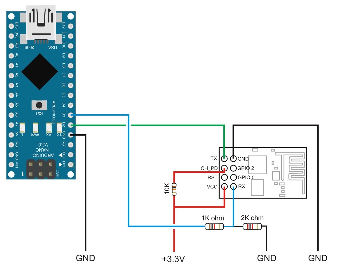
It’s not very difficult to get things working with the ESP. On this forum there is very comprehensive information about what you want to achieve. The transmit from the UNO to the Rx of the ESP does have to be pulled down to 3.3v with some sort of voltage divider, a simple resistor will work in most cases.
But of course the Tx/Rx go to the appropriate pins on your Arduino, not to digital pins as depicted in the picture above.
One more thing, if you are going to debug this, you need to enable Software Serial for debug output. You could also use software serial to attach the ESP to the Arduino, but that is really unstable.
Enter 5 in the Input Voltage box and 3.3 in the Output voltage box. You then enter the resistor value you might have for R1 and press the Compute button to see if you have the required resistor for R2.
Equally you can enter a value in R2 to establish the value of R1.
3.3 and 5 are not exact figures and neither are the resistors as they all have tolerances. A 2K resistor at R2 gives 1030.3 ohms value for R1. Removing the 3.3 output voltage and changing the 1030.3 on computation gives 3.333 volts which should be fine for the RX pin on the ESP.
Maybe get to this stage and then we can move on.
If you only have one ESP it isn’t worth the risk of not using a voltage divider. It might run for 10 minutes, 10 hours or 10 weeks without one but equally it might go “puff” in the “blink” of an eye.
Hopefully you have the correct firmware on the ESP as many do these days.
As you have a very short time to get this up and running I will let you work on the voltage divider whilst I look at the changes required for the sketch to work with an Uno.
Here is the required sketch with a couple of lines modified for use with an Uno. Pin 2 on the Uno is for receiving (rx) data from the ESP and pin 3 on the Uno is for transmitting (tx) data to the ESP.
So pin 2 Uno (rx) goes to the tx pin on the ESP and pin 3 Uno (tx) goes to the rx pin on the ESP. Voltage divider goes between Uno pin 3 and ESP rx pin.
/**************************************************************
 * Blynk is a platform with iOS and Android apps to control
 * Arduino, Raspberry Pi and the likes over the Internet.
 * You can easily build graphic interfaces for all your
 * projects by simply dragging and dropping widgets.
 *
 *   Downloads, docs, tutorials: http://www.blynk.cc
 *   Blynk community:            http://community.blynk.cc
 *   Social networks:            http://www.fb.com/blynkapp
 *                               http://twitter.com/blynk_app
 *
 * Blynk library is licensed under MIT license
 * This example code is in public domain.
 *
 **************************************************************
 *
 * This example shows how to use ESP8266 Shield (with AT commands)
 * to connect your project to Blynk.
 *
 * Note: Ensure a stable serial connection to ESP8266!
 *       Firmware version 1.0.0 (AT v0.22) is needed.
 *       You can change ESP baud rate. Connect to AT console and call:
 *           AT+UART_DEF=9600,8,1,0,0
 *       In general, Soft Serial may be unstable.
 *       It is highly recommended to switch to Hard Serial.
 *
 * Change WiFi ssid, pass, and Blynk auth token to run :)
 * Feel free to apply it to any other example. It's simple!
 *
 **************************************************************/

#define BLYNK_PRINT Serial    // Comment this out to disable prints and save space
#include <ESP8266_Lib.h>
#include <BlynkSimpleShieldEsp8266.h>

// You should get Auth Token in the Blynk App.
// Go to the Project Settings (nut icon).
char auth[] = "YourAuthToken";

// Your WiFi credentials.
// Set password to "" for open networks.
char ssid[] = "YourNetworkName";
char pass[] = "YourPassword";

// Hardware Serial on Mega, Leonardo, Micro...
//#define EspSerial Serial1

// or Software Serial on Uno, Nano...
#include <SoftwareSerial.h>
SoftwareSerial EspSerial(2, 3); // RX, TX

// Your ESP8266 baud rate:
#define ESP8266_BAUD 9600

ESP8266 wifi(&EspSerial);

void setup()
{
  // Set console baud rate
  Serial.begin(9600);
  delay(10);
  // Set ESP8266 baud rate
  EspSerial.begin(ESP8266_BAUD);
  delay(10);

  Blynk.begin(auth, wifi, ssid, pass);
}

void loop()
{
  Blynk.run();
}
No, it helps more people if all questions and answers are kept in one place i.e. here on the Blynk Community site.
If you have the voltage divider set up then it is safe for you to upload the sketch. It might not work but you shouldn’t damage the ESP. Provide any messages that appear in Serial Monitor by copying and pasting them in this thread.
Yes, it should work now. As Costas mentioned, keep the Serial monitor open (ctrl-shift-m on Windows I believe) and turn it on. If you didn’t do any flashing to the ESP it should run the standard AT firmware and act as a shield. In the Blynk sketch Costas provided you need to edit the Wifi network, SSID and Authentication token for connecting to Blynk servers.
the guys have done a tremendous job of explaining everything so clear your head, and go through their instructions as a check list. tinkering with electronics can be frustrating but also very rewarding.
you might also want to google some of the stuff for more details, it will help you learn better how things are linked and how they are supposed to work together.
the keypoints they mentioned are:
make sure your ESP chip runs the AT firmware
make sure you have a proper divider
make sure you have all conenctions as instructed
start your modules and make sure they can communicate
up to this point, don t even bother with Blynk (it’s easy to add after anyway, jsut use the example they provided)
This is correct as per the 3 or 4 references by different Blynkers in this thread.
Occasionally the internet has inaccurate information and there is a reason sometimes the connections are quoted differently, but you don’t need to know about that at this stage. Ask later if you are interested.
We are all taking an active overview of what you are doing so if any Blynkers suggest anything that is obviously wrong it will be picked up promptly and corrected i.e. you can take what is quoted in this thread to be 100% accurate and ignore the general internet for now.
@george you didn’t install the libraries correctly. There are now 5 “Blynk” libraries that have to be installed manually and not through Arduino IDE Boards manager.
As @Costas says, it could be a firmware issue. The only way to check if you have the correct firmware is to hook up the ESP Tx/Rx lines to a serial port and directly check with AT commands to see if that is the case.
Bad wiring is easily enough troubleshooted. Did you hook up both CH_PD and VCC to 3.3v?