@claytoncamilleri100 take a look on this page … especially you are using ESP8266-01
1 Like
Well I had this problem before and my solution was to connect a pot.(20-47k) to the base of the transistor,instead of 1k resistor.Adjust pot to get right bias value then replace with nearest value resistor.
Hope this helps.
@claytoncamilleri100 take a look on this page … especially you are using ESP8266-01
I already read that but I can’t use that with a transistor
Thanks I will try that
Why you can’t use that with a transistor ?! I’m using it with 2N2222 to drive a relay and it works fine for me till now ![]()

@claytoncamilleri100 Yes firstly i use ESP-01 with external pull up resistor at GPIO2 + 2N2222 to drive a relay and it works fine for me ,except one problem which is 2N2222 is switched on when it’s base is High and i’m already pull GPIO2 up so at restarting ESP (the 2 or 3 seconds it determine its operation mode) the 2N2222 is on (due to the pull up R) and my relay is switched on .
And also it was normally to control as “1” drives the 2N2222 on & “0” drives it off 
But then i changed to ESP12 & ESP12E which has a plenty of GPIO and i don’t need to concern about GPIO0 &GPIO2 and pull up R and also i reduce my PCB size 
I redid you circuit and it worked fine, no burnt components ![]() . Is there a way I can change the logic in the software and not send 0 to turn on the leds?
. Is there a way I can change the logic in the software and not send 0 to turn on the leds?
hi @psoro
i have the module and set up like your diagram ,
this is my code:
int fadeVal;
#define testIRF520 5 //pin for IRF520 testing

BLYNK_WRITE(V63) //MANUAL fan speed setting
{
  fadeVal = param.asInt(); // set fader
  if (fadeVal == 0)
  {
    digitalWrite(testIRF520, 0); //off
    Serial.println(F("FADE set to 0"));
    Serial.println(fadeVal);
  }
  else if (fadeVal == 1)
  {
    fadeVal = 1;
    fadeVal = map(fadeVal, 0, 3, 200, 1024);     // scale it
    digitalWrite(testIRF520, fadeVal);
    Serial.println(F("FADE set to 1"));
    Serial.println(fadeVal);
  }
  else if (fadeVal == 2)
  {
    fadeVal = 2;
    fadeVal = map(fadeVal, 0, 3, 200, 1024);     // scale it
    digitalWrite(testIRF520, fadeVal);
    Serial.println(F("FADE set to 2"));
    Serial.println(fadeVal);
  }
  else if (fadeVal == 3)
  {
    fadeVal = 3;
    fadeVal = map(fadeVal, 0, 3, 200, 1024);     // scale it
    digitalWrite(testIRF520, fadeVal);
    Serial.println(F("FADE set to 3"));
    Serial.println(fadeVal);
  }
}
serial monitor says i am setting the fader, but nothing happens at the IRF520 module?
Hi @Dave1829,
I thought I was never gonna say that to you…
Could you please post a decent format code? Lol
1 Like
lol, not sure what happen there! fixed.
so is it supposed to be analogWrite?
Better now…
Is the V63 a slider fixed from 1 to 3?
I think you must use other variable for the digitalWrite, you are always using the same (fadeVal) and I guess Blynk is overwriting its value
thanks for being so polite about my daftness!
seems to work now ![]()
working code:
int fadeVal; // this is teh Blynk variable
int fadeSet; // this is the value sent to the PIN
#define testIRF520 5 //pin for IRF520 testing

BLYNK_WRITE(V63) //MANUAL fan speed setting
{
  fadeVal = param.asInt(); // set fader
  if (fadeVal == 0)
  {
    analogWrite(testIRF520, 0); //off
    Serial.println(F("FADE set to 0"));
    Serial.println(fadeSet);
  }
  else if (fadeVal == 1)
  {
    fadeSet = 1;
    fadeSet = map(fadeSet, 0, 3, 1, 255);     // scale it
    analogWrite(testIRF520, fadeSet);
    Serial.println(F("FADE set to 1"));
    Serial.println(fadeSet);
  }
  else if (fadeVal == 2)
  {
    fadeSet = 2;
    fadeSet = map(fadeSet, 0, 3, 1, 255);     // scale it
    analogWrite(testIRF520, fadeSet);
    Serial.println(F("FADE set to 2"));
    Serial.println(fadeSet);
  }
  else if (fadeVal == 3)
  {
    fadeSet = 3;
    fadeSet = map(fadeSet, 0, 3, 1, 255);     // scale it
    analogWrite(testIRF520, fadeSet);
    Serial.println(F("FADE set to 3"));
    Serial.println(fadeSet);
  }
}
My pleasure. ![]()
Glad it’s working now.
hmmm, I just tried it with a LED downlight that runs off a “constant current” driver
the LED is flashing every few seconds, but its lux output is equivalent to my dimming setting.
is it flashing because of my components?
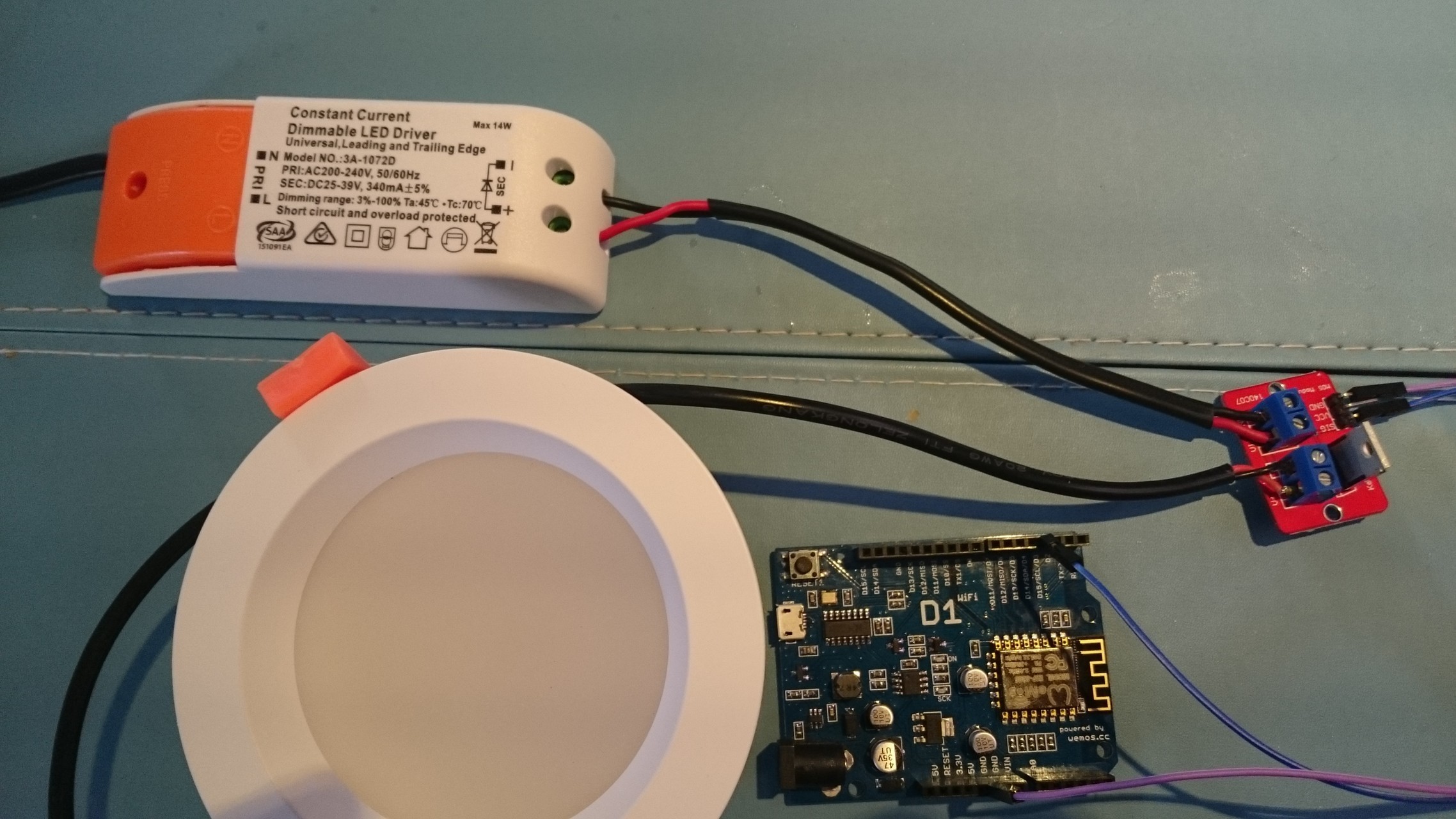
or the code?
Hi @Dave1829,
I have no experience with those devices but I think you should use the PWM signal to the AC line and not to the output. Unfortunately the little board can’t be used for that purpose.
Please check in detail before doing something wrong.
oh, OK, it is just that your image above shows the IRF520 with a DC lamp? maybe it is incandescent only?
i will do some more googling…
I’m pretty sure the IRF520 can’t handle logic level switching, e.g. the 3.3v output is not enough to drive the gate open. I use IRLB8721 mosfets do switch 12v led’s with an ESP.
oh, so that is why it is flashing?
doh.
Not tested yet but I think it should work fine with 3.3V… I will test it and come back to you
Edit:
After a few googling it seems @Lichtsignaal is correct and it is not gonna work with 3.3V… I’m really sorry for my bad sketch…
Hehe, it’s not a bad sketch, in this case it’s non-correct hardware. You guys don’t wanna know how much I’ve been swearing at the stupid mosfets…
Try with an Arduino, you’ll see it’ll work perfectly on 5v