I am developing a project that consists of an esp8266 esp-01 connected to a BD711 transistor to turn a 12V led strip.
I have connected the esp`s GPIO 2 to a 1k resistor to the base of the transistor. Led strip anode to +12v and negative to the collector of the transistor and emitter to ground. For power I have the ams1117 3.3v regulator. Ch_PD and reset are both connected to 3.3v directly.
My problem is that when GPIO 2 is connected to the transistor the esp wont start correctly and the blue led stays on. If I disconnect the transistor the module starts correctly. What can I do to leave it connected and restart the module without the problem?
Hello blynkers, my first post here.
As GPIO2 must be HIGH during startup, you cannot connect it to a circuit which pulls GPIO2 LOW. 1k resistor to the base of NPN transistor is pulling GPIO2 down, because the base behaves like a diode in conducting direction. I would suggest adding a small pnp transistor: emitter to 3v3, base through 2k2 to GPIO2, collector through 100-200ohm to base of BD711 (to limit the base current), additionally about 1k from BD711 base to ground (to ensure BD711 is able to switch off). Of course the logic must be inverted.
Did not work I burned one of my esp`s trying what @crazy4volvo suggested. Could this be because voltage from the base of the pnp transistor is going into GPIO2?
@psoro could you please indicate how the IRF520 is wired up and if it will give a HIGH or a LOW signal on the data pin by default. If that makes any sense to you
@Costas, @claytoncamilleri100,
I have done the test with the IRF520 and I have same issue… It doesn’t work…
I’ve got 1.22V at GPIO2 at Startup and the Blue light is ON…
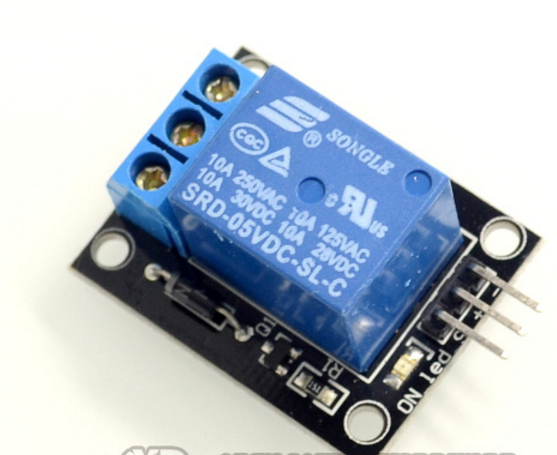
It would be better if you use a Relay Module, it works fine (tested!)