What I am doing wrong with this simple sketch

I thinks so

Okay, it does seem to be a D1 R1 and you’ve chosen the correct board in the IDE.
I’m not familiar with these boards, as I prefer the D1 Mini, but I’m guessing that the pins you are using (D6 & D7) are causing a problem.
Try changing these to other pins instead.
Do you have any widgets in the app that are connected to digital pins?

Pete.

I changed Pins 12 and 13
also 8 and 9 its shows same
my blynk app is very clear, i delete them all
BTW, I always use D before pin number, without D my serial monitor looks funny. like unknow symbols , scrolling ect
the problem is timer library i think
without these lines

BlynkTimer timer;
timer.setInterval(1000L,mycode1);
 timer.run();  

all working fine, I completed almost all blynk tutorials
exp: I can turn an and off LED
LED is connected to my D3 or any other
and button widget is connected to D3
sketch is simple sketch
but when I try to use timer its not connecting to the server
reason I using timer is, Blynk said keep the main loop clean.
it is the problem
BTW, today I bought NodeCMU and uploaded all the sketchs
its working fine,
so problem is now
Wemos d1r1 with blynk library, specially blynk timer, i think
Do I need toput away wemos d1 and use NodeCMU ?
after all I should contact with wemos d1 provider. :frowning:


That statement rings dome alarm bells with me.
The “funny symbols” are because the ESP8266 chip is outputting it’s boot data at a different baud rate to the rate set in your serial monitor. Change the serial monitor baud until these “funny symbols” make sense, and use this as the baud rate used in your void setup.
You’ll then have much more idea what the device is trying to tell you.

Pete.

Okay, I will keep try until right baund rate
How about my original question
How to connect wemos d1 with Blynk server while keeping the loop clean

I would try using the actual GPIO numbers instead of the silk screened “D” numbers. You can find a reference as to how the “D” number relate to the actual GPIO numbers online. Due note that D6 is not GPIO 6.

I found this online, but not sure if it is corrct.

Yeah, I was seeing Nodemcu;s GPIO numbers
they say dont use silk screened D number , they are wrong, use GPIO numbering
and some other say if you want to use silk screened number with wemos d1, which is printed on the board,
I should use D before pin number
I am very confused, first it was funny serial print when I dont use Dx
and I googled found Dx works with wemos board so i stick with it
but now you are saying I need to use GPIO
I found it from arduino forum
forum link : https://forum.arduino.cc/index.php?topic=545113.15&fbclid=IwAR3F4YS5TzL3pBwOikwxIGZDF08tsuaz4zEASoG6W1T4Cj59pAB_0HuL6Xc
So, D6 is not 6 its 12 right?
lets look at the silk screen, I mean board
D6 is there and I write simple program using D6 and blynk
creat button wich connected to D6
and connect LED to D6
when I push the button LED is turning on,
WHAT ARE U talking about D6 is not d6,
code and LED is working perfectly also with blynk.
If D6 is not D6 the where to connect LED on board?

static const uint8_t D0   = 3;
static const uint8_t D1   = 1;
static const uint8_t D2   = 16;
static const uint8_t D3   = 5;
static const uint8_t D4   = 4;
static const uint8_t D5   = 14;
static const uint8_t D6   = 12;
static const uint8_t D7   = 13;
static const uint8_t D8   = 0;
static const uint8_t D9   = 2;
static const uint8_t D10  = 15;
static const uint8_t D11  = 13;
static const uint8_t D12  = 12;
static const uint8_t D13  = 14;
static const uint8_t D14  = 4;
static const uint8_t D15  = 5;

nah, I read about NodeMCU, its dangerous to noob like me,
io pins are taking very low currents also pins are more complicated than wemos.
so i will keep nodemcu and try to figure out wemos pin
ok, before it was, If i want to use Pin 6, then I write code using D, it looks like

define myLEDpin D6
 pinMode(myLEDpin , OUTPUT);
 
  digitalWrite(myLEDpin , HIGH); 

and I connet LED into D6 and Grond to gnd. so LED is on
If i want it to be controlled by my phone
I use blynk and cread buttin which connects to digital pin 6
so when I push the button LED is turned on,
CODE is D6 , Blynk is D6, also silk screen/ D6 is printed on the board
EVERYTHING was using D6
Okay, It is working but it is wrong,
so I need to use GPIO.
simply how I can use that?
like define myLED GPIO 6 (I believe it is not they way to use GPIO nubers)
and then expect to D12 light/ turn on ?
its funny, I looked at the silk screen/board D6 and D12 are on one PIN

somebody help me to use GPIO numbers in my code pls,
how about define myLED D9 = 2; and then connect LED to D2 ???
as follows it

...
....
static const uint8_t D9   = 2;
...
....

what I said was

The “D” numbers are not the GPIO Numbers.

From experience, using the GPIO numbers is better as it allows you to change hardware much easier. If you use the “D” number then going from a D1R1 to a NodeMCU will require you to modify pin numbers in the code. As to where if you used GPIO number is would not. It may also help you to identify if you are using pins that may affect the booting mode of the device. For example, with an ESP8266, GPIO 0, 2, and 15 must be pulled to a certain state in order for the board to boot correctly.

No you would just put the pin number. For example:

#define  myLEDpin  12  //use GPIO 12

You’re wrong on both counts there.
Take a look at your NodeMCU. It has one if these on it:

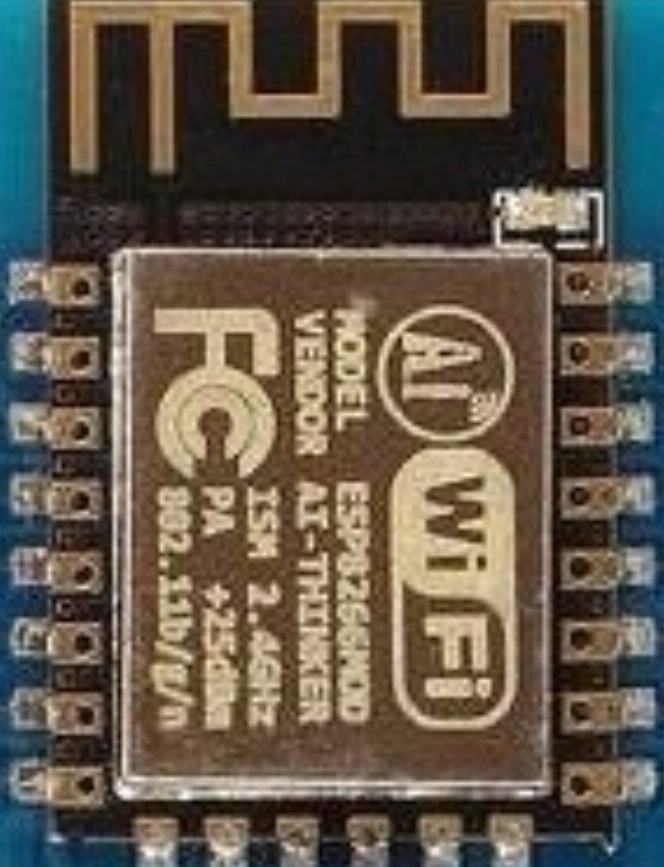
That’s the same ESP8266 processor as your Wemos D1 R1 and it has the same electrical characteristics. Both can sink the same amount of GPIO pin current and both are 5v tolerant. The only real differences are the form factor of the board, the silk-screening of the PIN numbers and the additional power connector on the D1 R1.

A good rule of thumb is always to use GPIO numbers when you’re referencing pins on the boards. This makes the code more portable between devices, and removes the type of confusion that you are currently experiencing.
Forget about the translation table of Dx numbers to GPIO numbers in your code, simply use the GPIO number, plus a comment that reminds you which pin this is on the various boars you are using.

You should also be aware of the restrictions regarding some GPIO pins on the ESP8266. Read this:

My advice would be to use your NodeMCU and this diagram:
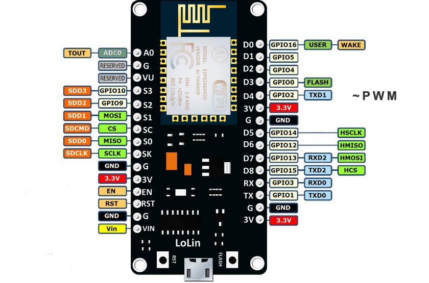
Pete.

1 Like

How about this , if it’s correct then it maybe easy to understand noob like me
Silkscreen is computing me so I deleted
Instead I gave new numbering to digital Pins
I connected my Ledgreen’ leg (hardware, like real led) on digital pin 1 ( my numbering) and other leg to gnd
And then wrote program
‘’’
#define Ledgreen 15
And digitalWrite (Ledgreen, HIGH)
‘’’
So if I flash the program and run it
My green led will turn on right?
And how about Bynk ?
I add widget button and choose Digital pins and choose D10 ( D10 from silkscreen)
How about virtual pin also D10 from silkscreen
How about this?
After work I will try this out.

NO… don’t try to reinvent the wheel. Print out the GPIO numbers as documented above and and use them in both your code and visual reference.

Virtual pins have nothing to do (directly) with physical/GPIO pins… they refer to functions that you write in your code… then in those functions you can control GPIO pins and do stuff.

EG, you have a Button/Switch in the App set for V0 and each time it changes state this function is called, and in the function the LED with also change state (using the built-in LED on your board, supposedly on GPIO 2… test this and see).

BLYNK_WRITE(V0) // called every state change of matching App widget set to V0 with states 0 and 1
{   
  int value = param.asInt(); // Get value of App Widget as integer
  digitalWrite(2, value); // set GPIO 2 to value of App Widget
}

Okay, I think I understand now
After 10 hours I will upload this sketch
Thanks

nope, note working with wemos d1

#define BLYNK_PRINT Serial


#include <ESP8266WiFi.h>
#include <BlynkSimpleEsp8266.h>
BlynkTimer timer;


char auth[] = "hWc7LZyHvUAzymPAjmuk4yKRxiIN3dFt";
char ssid[] = "iptime miigaa";
char pass[] = "Myagmarbayar12*";


void mycode1();
#define LEDgreen  12
#define LEDred  13


void mycode1()
{
  digitalWrite(LEDgreen, !digitalRead(LEDgreen)); // Reads current state and sets to opposite state
  digitalWrite(LEDred, !digitalRead(LEDred)); // Reads current state and sets to opposite state
}
     

void setup()
{
  // Debug console
  Serial.begin(9600);

pinMode(LEDgreen, OUTPUT); 
  pinMode(LEDred, OUTPUT);
  
  digitalWrite(LEDgreen, HIGH); 
  digitalWrite(LEDred, HIGH);

    Blynk.begin(auth, ssid, pass, "blynk-cloud.com", 8080);
 timer.setInterval(1000L,mycode1); 
  
}

void loop()
{
  Blynk.run();
  timer.run();
}

What exactly does “not working” mean?

I’ve just compiled your code, replaced your WiFi Credentials and Blynk Auth code with mine, and uploaded it to a NodeMCU. The only other changes I made were to increase the baud rate to 74880 (the native baud rate of my NodeMCU):

Serial.begin(74880);

and comment-out this line:

// void mycode1();

as I don’t like pre-declaring function names when I don’t have to - I find it confusing when I’m debugging.

I connected a Red LED to the pin labelled D7 and a green LED to the pin labelled D6
The other side of both LEDs are connected top the GND pin. I have a 180 Ohm resistor in the positive lead of each resistor.

The code works perfectly, It connects to Blynk and turns both LEDs on for one second then off for one second repeatedly
You obviously have to ensure that the LED is connected in the correct polarity (with the “Anvil” reflector connected to GND).

This is what the serial output looks like when your Serial.begin statement matches the native baud rate of your board:

 ets Jan  8 2013,rst cause:2, boot mode:(3,6)

load 0x4010f000, len 3584, room 16 
tail 0
chksum 0xb0
csum 0xb0
v5d3af165
~ld
[61] Connecting to [REDACTED]
[563] Connected to WiFi
[563] IP: 192.168.1.177
[563] 
    ___  __          __
   / _ )/ /_ _____  / /__
  / _  / / // / _ \/  '_/
 /____/_/\_, /_//_/_/\_\
        /___/ v0.6.1 on NodeMCU

[572] Connecting to blynk-cloud.com:8080
[664] Ready (ping: 27ms).

Pete.

I gave up to use wemos d1 with blynk.
It does not connect to the blynk server when I use blynk timer.
I have NodeMCU, so its time saving to move further with nodecmu. wemos d1 wasted
long time and money,
exactly 1 year ago I bought my first board as wemos d1
simple examples works but complicated other people code was not working with wemos d1, that i did not know and wasted time. // for newbies GPIO and silkscreen is comfusing/// Dx was solution but still not recommended, read GTT;s comment, who explained well. now I understan how to use GPIO pin numbering thanks man.

later on I bought Uno and every code works fine.
finally, I bough nodemcu now, bcz I want my control over wifi, wifi module can be solve my prolem , but i just want to use controller which has own wifi. I am planning to do it like 10 or 20, so all my friends could use their phone to control curtains and light, so thinking of expanse, I want controller it has own wifi

Anyway. I am not spending my all time with arduino, bcz other things to do.
thats why i am taking 1 year to finish my project, also noob , I needed to read every thing
like LED legs, if or while loop, so on
Thanks community, If you`are reading until here my post and also if you have wemos d1 retired board, please try this sketch and see if that connect to Blynk server,
Thanks guys,
I will post my next post soon, I hope my all code will work with NodeMCU
which post will be about

  • dc motor position. speed controlling
  • DIY encoder
  • PID controller
  • L293D
  • safely using relays
  • what else I learn in one year?
  • ah, maybe dvd step motor used small cnc
  • and other sensors
    when I post my next post or question I will leave link here.
    Happy blynk guys, not with wemos d1, I will suggest you trow it out, as I already pack it for long time kkep, one day i will use it, dont know yet the application.
    THE code, which is not working with wemos d1
#define BLYNK_PRINT Serial


#include <ESP8266WiFi.h>
#include <BlynkSimpleEsp8266.h>
BlynkTimer timer;
char auth[] = "hWc7ssssssssssssssssssssssssiIN3dFt";
char ssid[] = "issssssssa";
char pass[] = "Mssssss2*";
#define LEDgreen  12
#define LEDred  13
void mycode1()
{
  digitalWrite(LEDgreen, !digitalRead(LEDgreen)); // Reads current state and sets to opposite state
  digitalWrite(LEDred, !digitalRead(LEDred)); // Reads current state and sets to opposite state
}
     

void setup()
{
  // Debug console
  Serial.begin(9600); // you can change if you want , with nodemcu 74880

pinMode(LEDgreen, OUTPUT); 
  pinMode(LEDred, OUTPUT);
  
  digitalWrite(LEDgreen, HIGH); 
  digitalWrite(LEDred, HIGH);

    Blynk.begin(auth, ssid, pass, "blynk-cloud.com", 8080);
 timer.setInterval(1000L,mycode1); 
  
}

void loop()
{
  Blynk.run();
  timer.run();
}

There is nothing wrong with the Wemos D1 R1 Board when used with Blynk and it works perfectly with BlynkTimer. The issue is that you are referencing the GPIO pins incorrectly, and I suspect you are addressing pins in the reserved GPIO 6-11 range, by virtue of how you are addressing the pins.

Of course, it’s possible that your D1 R1 is damaged or faulty, but I doubt it.

However, the NodeMCU or Wemos D1 Mini/Pro are nicer boards to work with as their pin numbering is less obscure and they have a much smaller form factor. I assume that you now have your LEDs flashing correctly on your NodeMCU?

Pete.

oh, yes,
leds are flashing.
thanks Pete, if you did not replay I could be truggling with it still
wemos should have community like this,
it exists?
anyway, if there is any way to get wemos d1 pls get it and uplaod that program, pls
for now I assume my board has problem,
ufny part is, it connects when I use examples-blynk-internet-8266 standallone sketch
okay, forget about it and see my next post, i will be back soon
ah, also i am updating my arduino IDE (wait a second blynk library Blynk_Release_v0.6.1 is still latest library?)

I don’t have a Wemos D1 R1 to test, but if you change this:

to this:

#define LEDgreen 2 
#define LEDred  14

with nothing connected to the board (other than USB for power) then it should flash the two onboard LEDs on the D1 R1.

Pete.