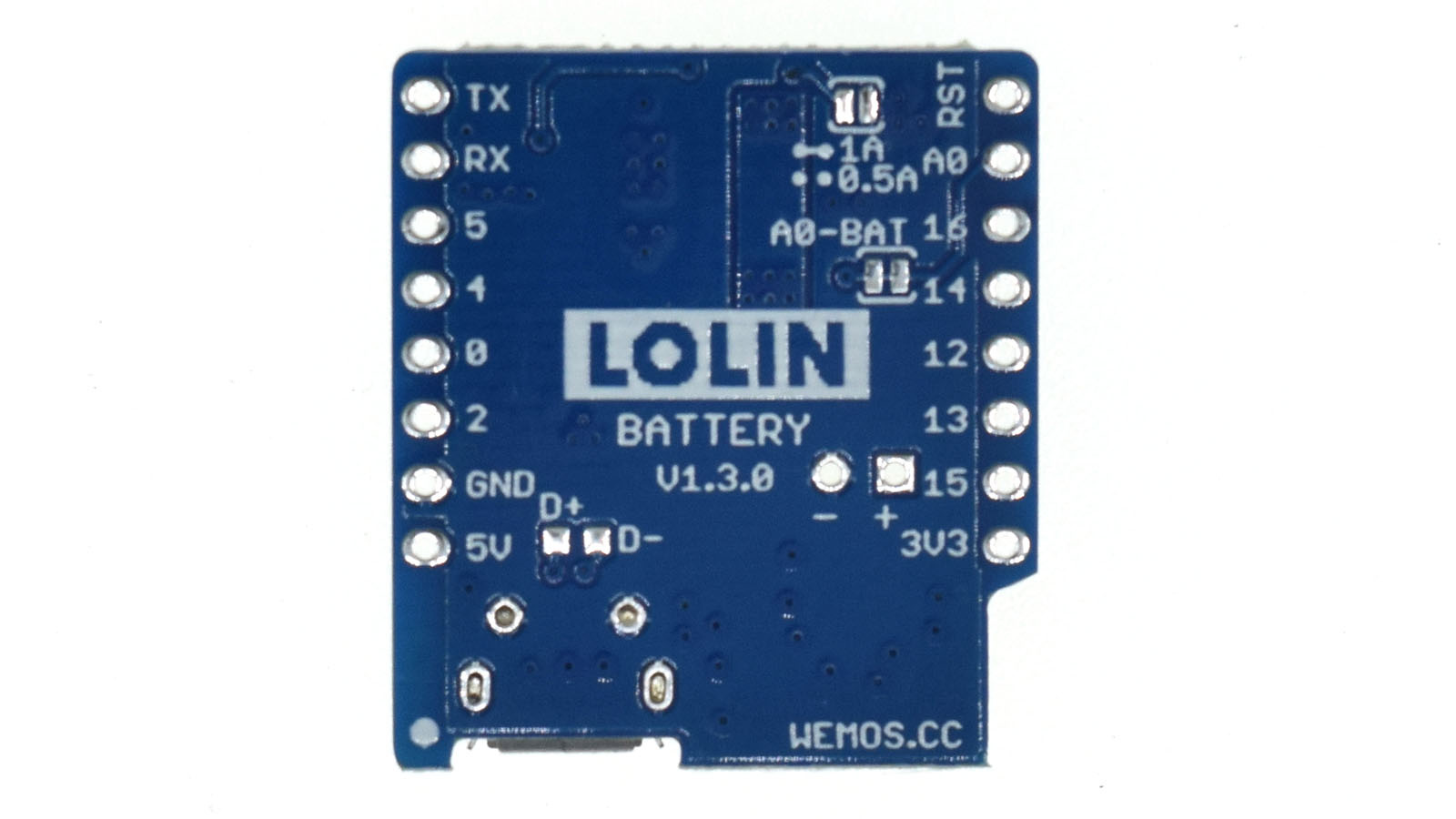
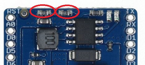
The two sets of pads up near the top right hand corner of the photo above , near the RST pin are the output current jumper.
If these contacts are open (as in the photo) then the output current will be 0.5A
If they are bridges with a blob of solder then the current will be 1A
There’s a little graphic screen-printed on there to illustrate this.
The contacts below that link A0 to the battery if bridges with a blob of solder.
Deep sleep puts the Wemos to sleep, so that only the internal clock is running. Think of it as hibernation mode. When it’s asleep, no code can execute and it can’t talk to Blynk.
You tell it how long to sleep for (it will depend on how often you want temperature and humidity readings - maybe every hour?) then it wakes-up after that time and reboots the Wemos.
Your code will then be setup to take some readings, send them to Blynk, then go back to sleep again.
Depending on your sensors and how quickly your device can connect to Wi-Fi and Blynk, your Wemos could be awake for as little as 5 seconds every time it wakes up.
Power consumption in sleep mode is a fraction of that in wake mode.
Wow, I have used a couple of these for over a year and never new about that I wonder the reason? Since having high current output capability doesn’t mean less battery capacity… unless your components actually draw the higher current in the first place. Something drawing only 300mA will still only draw 300mA regardless if current capacity is 500mA or 500A
Ah… it is in relation to the battery CHARGING current, not the supply to MCU current… that makes more sense… You don’t want to push too much current into the typically small LiPo batteries these usually hook up to.
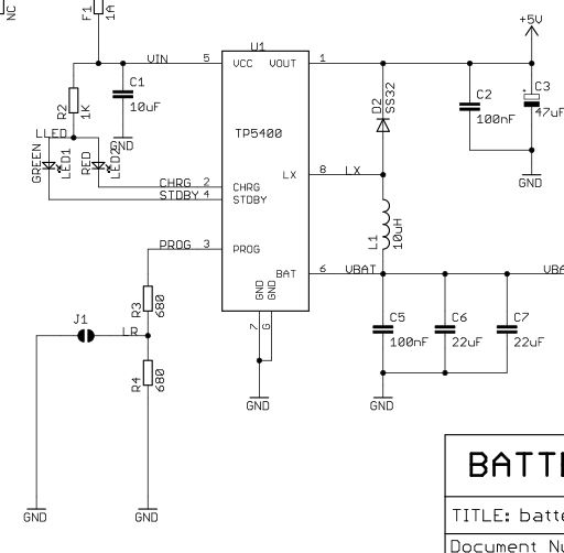
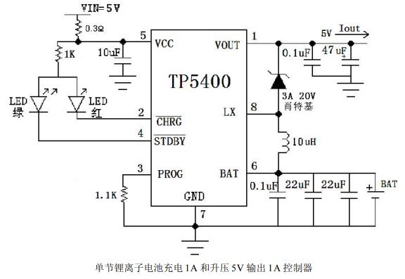
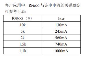
One thing I noticed is that the resistor values listed on the wemos battery shield schematic, and those listed with the TP5400 data sheet don’t seem to match.
Although, it is in Chinese, and I am doing a bit of google translate. so maybe I am missing something.
I think Wemos made the “boost charge” option selectable, whereas the default schematic shows just the full current setting.
Looks like the Wemos IS putting out between 560-740mA by default (with a resistance setting of 1360 ohms). But how does dropping that to 680 ohms change anything??? It looks backwards to me.
I see how wemos made the charge current selectable by using the jumper. It is just that the values they used for resistors are off. @1360 (1.3k) ohms the charge rate would be somewhere between 740mA (@1.5 kohm) and 1000mA (@1.1 kohm), more than 1.5 times the 500mA advertised.
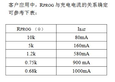
With the jumper enabled, the resistance drops to 680 ohms. That is much lower than the 1.1 kohm needed for the 1000mA charge rate. I am curious if this would have any effect on how the chip behaves.
Doing a bit more digging, the previous version of the wemos battery shield V1.1.0, use the TP5410 chip. For the TP5410, these would be the correct value resistors to get 500mA and 1000mA charge currents.
So either they forgot to update the resistor values when switching to the new chip, or forgot to update their drawing with the resistor values they are actually using.
EDIT Looking at the picture of the new version, they appear to be 680 ohm resistors, so it seems as if they didn’t use the correct value resistors for the TP5400 chip they updated to.
Hello guys!! I need one more help in this issue. I’ve connect a wemos battery shield with wemos d1 mini, and connect a li-po battery with the battery shield to power it on. I’ve also connect a switch between battery & battery shield so that I can turned off my project when I don’t need it. But how can I only charge the battery without turning on the wemos d1 mini? Because, to charge the battery, the switch must be turned on which will also powered on the wemos d1 mini. That means, my project is running in the charging time. Again to disconnect the charging shield every time to charge the battery is not a feasible idea. So, if u guys have any suggestion plz share it. Thanks.
I think the solution would be to use deep sleep to “turn off” your Wemos, maybe with a dedicated pin to put the Wemos to sleep (and a button to connect RST to GND to wake it up).


 At least that never happens here