So, i’ve using the esp-01 and the L298n driver, the GPIO connected directly to the in1, in2 on the motor, and now got burned.
now with my new ESP-12, i’m want to use, the Logic level converter,
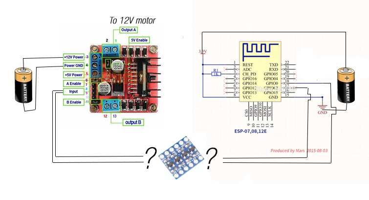
what i wanted to do is hooking up my GPIO2 and GPIO0 , to the Logic Level Converter, and then to the in1, and in2 of my L298 motor driver,
the problem is my multimeter was lost, and i dont want to waste another esp8266 just because of the wrong wiring,
So, can anyone help me to wire this with Logic Level Converter thing?
I have independently 12v power input to the L298 and independently 3.3v power input to my ESP.
Can i just wiring the GPIO to LV1 LLC and the motor in1 to HV1 LLC?
or
I still need other 5v and the 3.3v input added to the Logic Level Converter ?
it may simple, but i just want to make sure about the wiring, since, i will need a new 5v power supply if i needed the logic level converter to powered up.
So, like i said before, i have independent power supply, one is 12v for the motor driver, and the other one is 3.3v for the ESP-12, and they have own ground that not connected to each other, the 5v power for my L298 supplied from the internal L298 (jumper attached). should i add one more 5v power supply ? or how can i wire it without more 5v power supply.
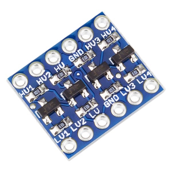
Common ground between ALL boards, ESP, L298 and LLC.
Based on your picture and the diagram I posted earlier for you… (different model, same concept).
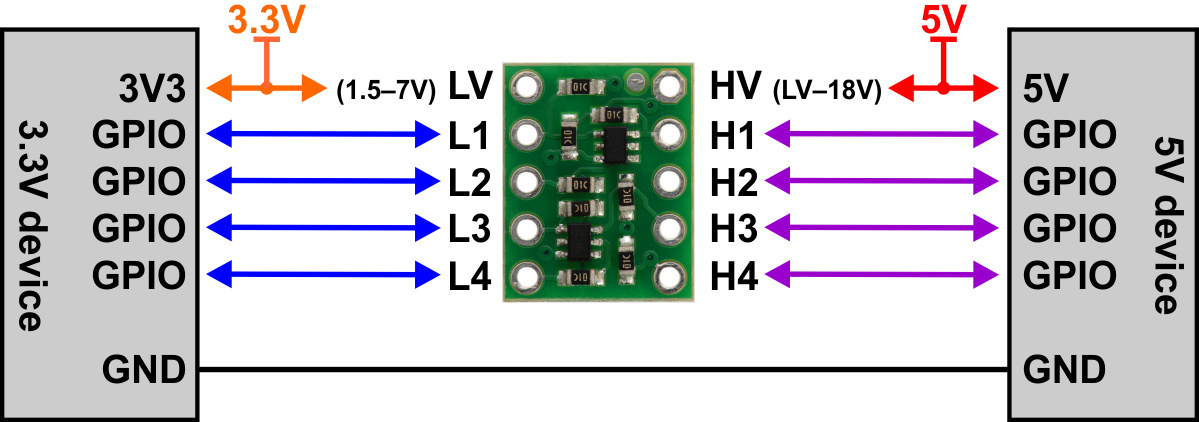
On the L298 board, even though is is originally meant as the 5v input… check the +5v Power pin with an LED or something, if your meter is dead, to see if it has power to it when the 5v Enable jumper is in place. If so, you should be fine tapping the 5v from it, to the HV pin on the LLC board.
Connect the 3v3v from your ESP PSU to the LV pin on your LLC board.
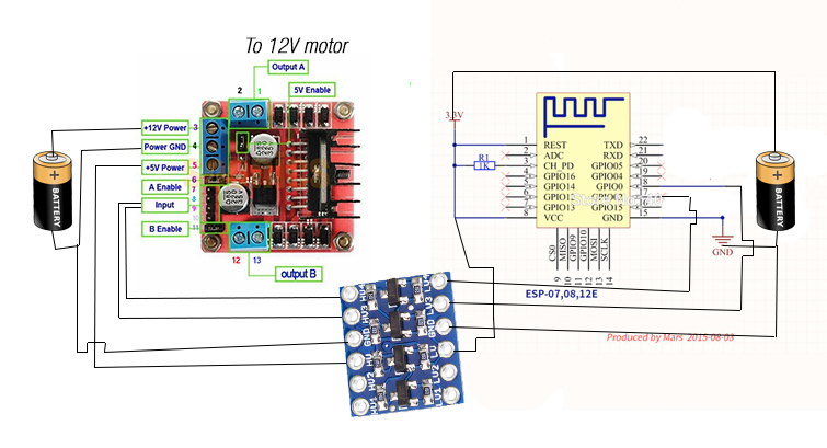
Then on the LLC board, just match up the numbers of the needed LVx pins to the ESP with the HVx pins to the L298 board.
To be honest I can’t see the need of the level converter… I’ve got several boards like this, once at home I’ll do some tests and come back to you, I could be wrong…
@psoro That is a good point… The L298 is input only, not sending any data back to the ESP, and it very likely 3.3v sensitive, so correct… no need for a LLC.
Sometimes I can’t see the forest for the trees
But I wonder how the ESP-01 got damaged then?? unless there was somehow transient power feeding back to the ESP pins? Might happen if there was no common ground at the time.
@psoro@Gunner so, it supposed to be alright without the LLC (like on my first picture, but without LLC ?)
i don’t know, but when i hooked it directly, (schematic on my first picture but without llc) my esp-01, got hot and only a few run of the motor, it dead…
The wiring in your last diagram looks OK. And I have tested and confirmed that there would be 5v available on the 5v Power pin of the L298 board, from its built in regulator.
However, that sounds more like some other power/wiring issue, not a case of 5v signal on a 3.3v pin… should not be enough real current there to build up heat. And as stated, the motor controller doesn’t send any signal to the ESP anyhow… LLC or not… it only receives a signal.
Again, without a previously shared ground, you might have had transient voltage/current where it shouldn’t have been been. Hard to be sure.
Since I don’t have the actual ESP toys to play with, I am going off of theory… but having RESET tied directly to 3.3v without any current limiting resistor seems more suspicious to me. I know some Google schematics show it that way, but others show a current limiting resistor in line.
So, now i’m sure both wiring (with or without the LLC) will be fine now for my esp-12,
and the issue to my esp-01 isn’t from the GPIO connection…
Thanks for the helpfull answer.