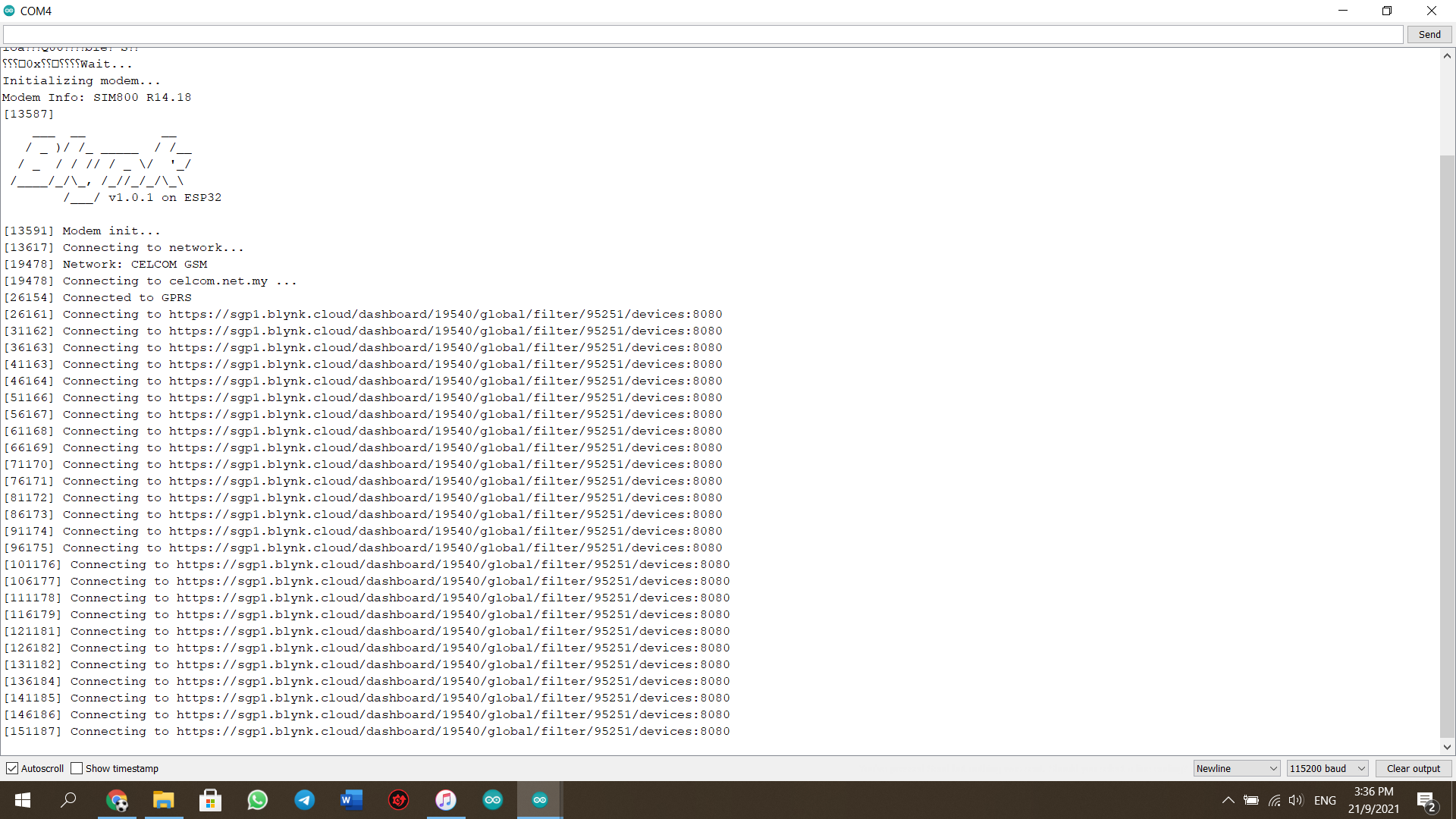
I still could not be able to connect the device to my dashboard.
The display on the serial monitor:
Joel.
I still could not be able to connect the device to my dashboard.
The display on the serial monitor:
Joel.
What does your Blynk.begin command look like?
Pete.
Have you tried a lower Baud rate? I use 9600 for Serial and SerialAT.
Also, I have a #define GSM_PIN “” statement in my code that works.
I assume you have no PIN and defined the correct TTGO T-Call board.
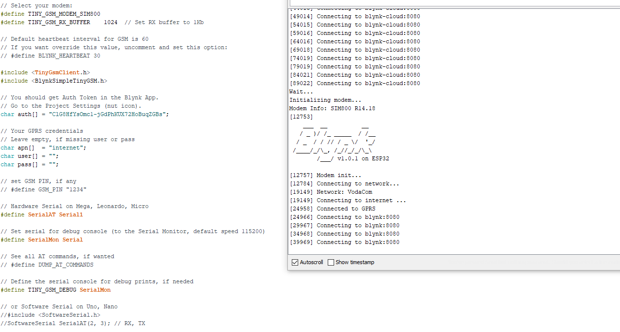
Not sure, maybe this will help:
not woriking
Blynk.begin(auth, modem, apn, user, pass, “Dashboard”, 8080);
This is what the Blynk.begin command looks like.
Joel.
That will never work!
I suggest that you re-read what I wrote, and follow the link I provided, then copy/paste one of those URLs from that link into your Blynk.begin command.
Pete.
Sure I will do that. Thank you and I will let you know.
Yes the baud rate that I have used is 115200 and with regards to the #define GSM_PIN “” statement, I will use that in my coding. Yes I have chosen the right TTGO T-Call board. I am using the #define SIM800L_IP5306_VERSION_20190610
Thank you @vshymanskyy, the coding that I have is similar to the one that you have given me. I will look further into it.
My Blynk.begin command looks like this now:
Blynk.begin(auth, modem, apn, user, pass, “https://sgp1.blynk.cloud/”, 8080);
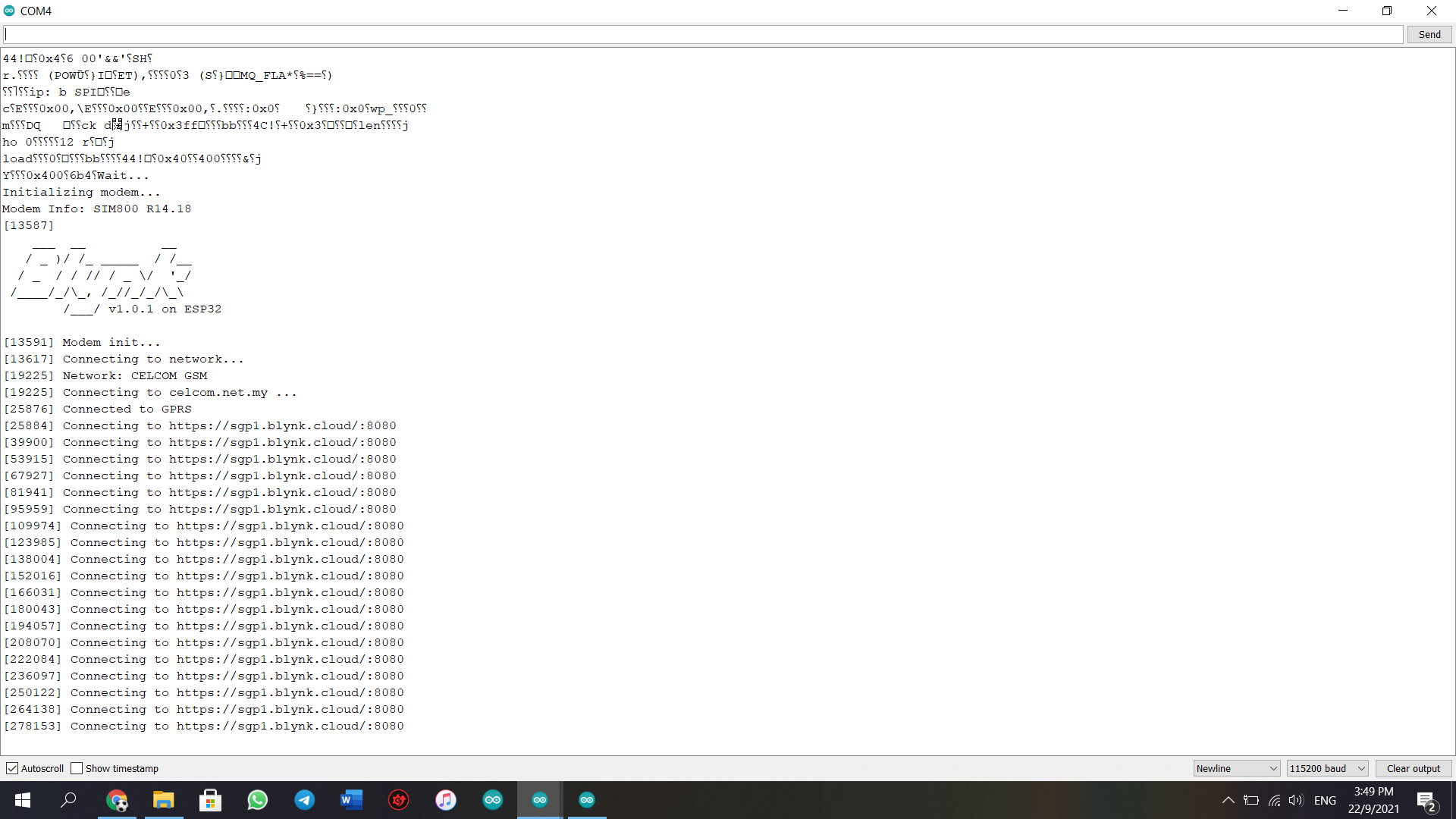
However, my device still could not be connected to the Blynk dashboard.
The dispaly on the serial monitor:
I’ve had best success with Baud rate 9600 and port 80. Somehow moving to better reception or using better antenna does make a difference for connection to Blynk cloud even if it connects to internet easily.
The GSM_PIN statement is only required for connection to internet, which you don’t seem to have a problem with.
I have tried using the baud rate at 9600 but it still could not be connected via GSM.
Hello everyone, I managed to connect with the Blynk dashboard via GSM. The problem was that I did not have credit in my SIM card and that is why it could not be connected with the dashboard. Once I added credit into it, it got connected to the dashboard and mobile application.
I want to say thank you to everyone who helped me 
Hi Joel,
Just for my understanding, did you make changes to code (as suggested by members) and load data or only data?
I am having a issue connecting to blynk cloud. Wifi, no oroblem, problem only via GSM.
Best regards,
Chris
Hello Chris,
I will give you the exact coding that I used to upload into my device. Make sure your SIM card is activated and has enough credit in it.
The coding:
#define BLYNK_PRINT Serial

/* Fill-in your Template ID (only if using Blynk.Cloud) */
#define BLYNK_TEMPLATE_ID "TMPLzXui7aCz"
#define BLYNK_DEVICE_NAME "GSM Turn Relay Module ON and OFF "
#define BLYNK_AUTH_TOKEN "epbp2MQbhMZHE2jQidVKlgXcLqGIkTDQ";

// Please select the corresponding model
 #define SIM800L_IP5306_VERSION_20200811

// Select your modem:
#define TINY_GSM_MODEM_SIM800
#define TINY_GSM_RX_BUFFER    1024  // Set RX buffer to 1Kb

// Default heartbeat interval for GSM is 60
// If you want override this value, uncomment and set this option:
// #define BLYNK_HEARTBEAT 30

#include <TinyGsmClient.h>
#include <BlynkSimpleTinyGSM.h>

// You should get Auth Token in the Blynk App.
// Go to the Project Settings (nut icon).
char auth[] = "epbp2MQbhMZHE2jQidVKlgXcLqGIkTDQ";

// Your GPRS credentials
// Leave empty, if missing user or pass
char apn[]  = "celcom.net.my";
char user[] = "";
char pass[] = "";

// set GSM PIN, if any
// #define GSM_PIN "1234"

// Hardware Serial on Mega, Leonardo, Micro
#define SerialAT Serial1

// Set serial for debug console (to the Serial Monitor, default speed 115200)
#define SerialMon Serial

// See all AT commands, if wanted
// #define DUMP_AT_COMMANDS

// Define the serial console for debug prints, if needed
#define TINY_GSM_DEBUG SerialMon

// or Software Serial on Uno, Nano
//#include <SoftwareSerial.h>
//SoftwareSerial SerialAT(2, 3); // RX, TX

#include "utilities.h"

#define relay1 18
#define relay2 14
#define relay3 15
#define relay4 19

#ifdef DUMP_AT_COMMANDS
#include <StreamDebugger.h>
StreamDebugger debugger(SerialAT, SerialMon);
TinyGsm modem(debugger);
#else
TinyGsm modem(SerialAT);
#endif
TinyGsmClient client(modem);

BLYNK_WRITE(V0)
{
  int pinValue = param.asInt(); // assigning incoming value from pin V1 to a variable
  digitalWrite(relay1, !pinValue);
  // process received value
}

BLYNK_WRITE(V1)
{
  int pinValue = param.asInt(); // assigning incoming value from pin V1 to a variable
  digitalWrite(relay2, !pinValue);
  // process received value
}

BLYNK_WRITE(V2)
{
  int pinValue = param.asInt(); // assigning incoming value from pin V1 to a variable
  digitalWrite(relay3, !pinValue);
  // process received value
}

BLYNK_WRITE(V3)
{
  int pinValue = param.asInt(); // assigning incoming value from pin V1 to a variable
  digitalWrite(relay4, !pinValue);
  // process received value
}

void setup()
{
  // Debug console
  Serial.begin(115200);

  pinMode(relay1, OUTPUT);
  pinMode(relay2, OUTPUT);
  pinMode(relay3, OUTPUT);
  pinMode(relay4, OUTPUT);

  digitalWrite(relay1, HIGH);
  digitalWrite(relay2, HIGH);
  digitalWrite(relay3, HIGH);
  digitalWrite(relay4, HIGH);

  delay(10);

  setupModem();

  SerialMon.println("Wait...");

  // Set GSM module baud rate and UART pins
  SerialAT.begin(115200, SERIAL_8N1, MODEM_RX, MODEM_TX);

  delay(6000);

  // Restart takes quite some time
  // To skip it, call init() instead of restart()
  SerialMon.println("Initializing modem...");
  modem.restart();
  // modem.init();

  String modemInfo = modem.getModemInfo();
  SerialMon.print("Modem Info: ");
  SerialMon.println(modemInfo);

  // Unlock your SIM card with a PIN
  // modem.simUnlock("1234");

  Blynk.begin(auth, modem, apn, user, pass);
}

void loop()
{
  Blynk.run();
}
utilities.h coding:
#include <Wire.h>

#if defined(SIM800L_IP5306_VERSION_20190610)

#define MODEM_RST             5
#define MODEM_PWRKEY          4
#define MODEM_POWER_ON       23
#define MODEM_TX             27
#define MODEM_RX             26

#define I2C_SDA              21
#define I2C_SCL              22
#define LED_GPIO             13
#define LED_ON               HIGH
#define LED_OFF              LOW

#define IP5306_ADDR          0x75
#define IP5306_REG_SYS_CTL0  0x00

// setPowerBoostKeepOn
bool setupPMU()
{
    bool en = true;
    Wire.begin(I2C_SDA, I2C_SCL);
    Wire.beginTransmission(IP5306_ADDR);
    Wire.write(IP5306_REG_SYS_CTL0);
    if (en) {
        Wire.write(0x37); // Set bit1: 1 enable 0 disable boost keep on
    } else {
        Wire.write(0x35); // 0x37 is default reg value
    }
    return Wire.endTransmission() == 0;
}


#elif defined(SIM800L_AXP192_VERSION_20200327)

#define MODEM_RST            5
#define MODEM_PWRKEY          4
#define MODEM_POWER_ON       23
#define MODEM_TX             27
#define MODEM_RX             26
#define MODEM_DTR            32
#define MODEM_RI             33

#define I2C_SDA              21
#define I2C_SCL              22
#define LED_GPIO             13
#define LED_ON               HIGH
#define LED_OFF              LOW


#elif defined(SIM800C_AXP192_VERSION_20200609)
// pin definitions
#define MODEM_PWRKEY          4
#define MODEM_POWER_ON       25
#define MODEM_TX             27
#define MODEM_RX             26
#define MODEM_DTR            32
#define MODEM_RI             33

#define I2C_SDA              21
#define I2C_SCL              22
#define LED_GPIO             12
#define LED_ON               LOW
#define LED_OFF              HIGH

#elif defined(SIM800L_IP5306_VERSION_20200811)


#define MODEM_RST             5
#define MODEM_PWRKEY          4
#define MODEM_POWER_ON       23
#define MODEM_TX             27
#define MODEM_RX             26

#define MODEM_DTR            32
#define MODEM_RI             33

#define I2C_SDA              21
#define I2C_SCL              22
#define LED_GPIO             13
#define LED_ON               HIGH
#define LED_OFF              LOW

#define IP5306_ADDR          0x75
#define IP5306_REG_SYS_CTL0  0x00

// setPowerBoostKeepOn
bool setupPMU()
{
    bool en = true;
    Wire.begin(I2C_SDA, I2C_SCL);
    Wire.beginTransmission(IP5306_ADDR);
    Wire.write(IP5306_REG_SYS_CTL0);
    if (en) {
        Wire.write(0x37); // Set bit1: 1 enable 0 disable boost keep on
    } else {
        Wire.write(0x35); // 0x37 is default reg value
    }
    return Wire.endTransmission() == 0;
}

#else

#error "Please select the corresponding model"

#endif


#if defined(SIM800L_AXP192_VERSION_20200327) || defined(SIM800C_AXP192_VERSION_20200609)
#include <axp20x.h>         //https://github.com/lewisxhe/AXP202X_Library

AXP20X_Class axp;

bool setupPMU()
{
// For more information about the use of AXP192, please refer to AXP202X_Library https://github.com/lewisxhe/AXP202X_Library
    Wire.begin(I2C_SDA, I2C_SCL);
    int ret = axp.begin(Wire, AXP192_SLAVE_ADDRESS);

    if (ret == AXP_FAIL) {
        Serial.println("AXP Power begin failed");
        return false;
    }

    //! Turn off unused power
    axp.setPowerOutPut(AXP192_DCDC1, AXP202_OFF);
    axp.setPowerOutPut(AXP192_LDO2, AXP202_OFF);
    axp.setPowerOutPut(AXP192_LDO3, AXP202_OFF);
    axp.setPowerOutPut(AXP192_DCDC2, AXP202_OFF);
    axp.setPowerOutPut(AXP192_EXTEN, AXP202_OFF);

    //! Do not turn off DC3, it is powered by esp32
    // axp.setPowerOutPut(AXP192_DCDC3, AXP202_ON);

    // Set the charging indicator to turn off
    // Turn it off to save current consumption
    // axp.setChgLEDMode(AXP20X_LED_OFF);

    // Set the charging indicator to flash once per second
    // axp.setChgLEDMode(AXP20X_LED_BLINK_1HZ);


    //! Use axp192 adc get voltage info
    axp.adc1Enable(AXP202_VBUS_VOL_ADC1 | AXP202_VBUS_CUR_ADC1 | AXP202_BATT_CUR_ADC1 | AXP202_BATT_VOL_ADC1, true);

    float vbus_v = axp.getVbusVoltage();
    float vbus_c = axp.getVbusCurrent();
    float batt_v = axp.getBattVoltage();
    // axp.getBattPercentage();   // axp192 is not support percentage
    Serial.printf("VBUS:%.2f mV %.2f mA ,BATTERY: %.2f\n", vbus_v, vbus_c, batt_v);

    return true;
}

#endif


void setupModem()
{

    // Start power management
    if (setupPMU() == false) {
        Serial.println("Setting power error");
    }

#ifdef MODEM_RST
    // Keep reset high
    pinMode(MODEM_RST, OUTPUT);
    digitalWrite(MODEM_RST, HIGH);
#endif

    pinMode(MODEM_PWRKEY, OUTPUT);
    pinMode(MODEM_POWER_ON, OUTPUT);

    // Turn on the Modem power first
    digitalWrite(MODEM_POWER_ON, HIGH);

    // Pull down PWRKEY for more than 1 second according to manual requirements
    digitalWrite(MODEM_PWRKEY, HIGH);
    delay(100);
    digitalWrite(MODEM_PWRKEY, LOW);
    delay(1000);
    digitalWrite(MODEM_PWRKEY, HIGH);

    // Initialize the indicator as an output
    pinMode(LED_GPIO, OUTPUT);
    digitalWrite(LED_GPIO, LED_OFF);
}
Use the utilities.h coding in a new tab.
Best regards,
Joel.
This was so helpful…Thank you…Mine is working now
Hi Joel, thank you! I will test today and let you know the result.