I owe you BIG time thanks 
1 Like
@speed57
Hello speed57
can you share your final code .
it is always nice to have more code examples for others to see and learn from.
thanks
Here you go, sorry for late response been busy.
#define BLYNK_PRINT Serial
#include <ArduinoOTA.h>
#include <ESP8266WiFi.h>
#include <BlynkSimpleEsp8266.h>

#define CLOUD  // comment out for local server

BlynkTimer timer;

char auth[]       = "xxxx";
char ssid[]       = "xxxx";
char pass[]       = "xxxx";
char server[]     = "blynk-cloud.com";    // ip or domain
char myhostname[] = "ACS712";  // for OTA and router identification

const int sensorIn = A0;
unsigned int mVperAmp = 66;   // 185 for 5A, 100 for 20A and 66 for 30A Module
float ACSVoltage = 0;
float VRMS = 0;
float AmpsRMS = 0;
float inputV = 238.0;           // reading from DMM
float mcuVoltage = 5.0;         // MCU ADC maximum - voltage divider means we should use 5.0V reference not 3.2V
float WH = 0;
unsigned int calibration = 62;  // V2 slider calibrates this
unsigned int pF = 95;           // Power Factor default 90
float energyCostpermonth = 0;   // 30 day cost as present energy usage incl approx PF
unsigned int energyTariff = 21; // http://www.energysavingtrust.org.uk/about-us/our-calculations

float CumumlativeCostToday = 0;
float t2secCost = 0;

void getACS712() {  // for AC
  ACSVoltage = getVPP();
  VRMS = (ACSVoltage/2.0) *0.707;
  VRMS = VRMS - (calibration / 10000.0);     // calibtrate to zero with slider
  AmpsRMS = (VRMS * 1000)/mVperAmp;
  if((AmpsRMS > -0.015) && (AmpsRMS < 0.008)){  // remove low end chatter
    AmpsRMS = 0.0;
  }
  Serial.print(String(AmpsRMS, 3));
  Serial.print(" Amps RMS");
  Serial.print("\tPower: ");
  WH = (inputV * AmpsRMS) * (pF / 100.0);
  Serial.print(String(WH, 3));
  Serial.print(" WH");
  Blynk.virtualWrite(V0, String(AmpsRMS, 3));
  Blynk.virtualWrite(V1, String(WH, 3));
  Blynk.virtualWrite(V3, int(WH + 0.5));  // gauge
  energyCostpermonth = 24.0 * 30.0 * (WH / 1000.0) * (energyTariff / 10000.0);
  t2secCost = ((WH / 1000.0) * energyTariff ) * ( 2 / 3600.0);
  CumumlativeCostToday = CumumlativeCostToday + t2secCost;
  Serial.print("  Approx cost per month: £");
  Serial.println(String(energyCostpermonth, 2));
  Blynk.virtualWrite(V6, String(energyCostpermonth, 2));
  Blynk.virtualWrite(V16, String(CumumlativeCostToday, 6)+ String(" "));
}

float getVPP()
{
  float result;
  int readValue;
  int maxValue = 0;
  int minValue = 1024;
  uint32_t start_time = millis();
  while((millis()-start_time) < 950) //read every 0.95 Sec
  {
     readValue = analogRead(sensorIn);
     if (readValue > maxValue)
     {
         maxValue = readValue;
     }
     if (readValue < minValue)
     {
         minValue = readValue;
     }
  }
   result = ((maxValue - minValue) * mcuVoltage) / 1024.0;
   return result;
 }

// V0 AC IRMS display
// V1 WH display

BLYNK_WRITE(V2) {  // calibration slider 50 to 70
    calibration = param.asInt();
}

// V3 WH gauge

BLYNK_WRITE(V4) {  // set supply voltage slider 70 to 260
    inputV = param.asInt();
}

BLYNK_WRITE(V5) {  // set 5, 20 or 30A ACS712 with menu
    switch (param.asInt())
    {
      case 1: {       // 30A
        mVperAmp = 66;
        break;
      }
      case 2: {       // 20A
        mVperAmp = 100;
        break;
      }
      case 3: {       // 5A
        mVperAmp = 185;
        break;
      }
      default: {      // 30A
       mVperAmp = 66;
      }
    }
}

// V6 Cost gauge

BLYNK_WRITE(V7) {  // PF slider 60 to 100 i.e 0.60 to 1.00, default 95
    pF = param.asInt();
}

BLYNK_WRITE(V8) {  // Energy tariff slider 1000 to 2000, default 1437 (UK £ 0.1437 / KWH)
    energyTariff = param.asInt();
}

void setup() {
  WiFi.hostname(myhostname);
  Serial.begin(115200);
  Serial.println("\n Rebooted");
  WiFi.mode(WIFI_STA);
  #ifdef CLOUD
    Blynk.begin(auth, ssid, pass);
  #else
    Blynk.begin(auth, ssid, pass, server);
  #endif
  while (Blynk.connect() == false) {}
  ArduinoOTA.setHostname(myhostname);
  ArduinoOTA.begin();
  timer.setInterval(2000L, getACS712); // get data every 2s
}

BLYNK_CONNECTED(){
  Blynk.syncAll();
}

void loop() {
  Blynk.run();
  ArduinoOTA.handle();
  timer.run();
}
Hope you will add more different values 
2 Likes
Hello All
A more precised discussion can be found here ESPecoMon
and here ESPproMon
& Here ESPproMon
& on google play ESPproMon
Thanks
 That is his GitHub page.
 , but I couldn’t find it with a simple search for ACS712
Hi guys,
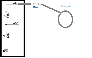
I just ordered a current sensor ,type ACS712 30A and I have read also the code into ESPECOMON.ino file to understand the logic ,but one thing that I still don’t understand is related to usage of 180K Ohm as stated in the comment line below
// Add a 180K Ohm resistor between ACS712 data out and Analogue port A0
It looks that it will play the role of voltage divider to step down from 5V(Max output of ACS712 sensor) to 3.3V, how that value of resistor was calculated giving180K Ohm ? Please someone help with the math behind.
Thanks in advance for your support and help !
Koz
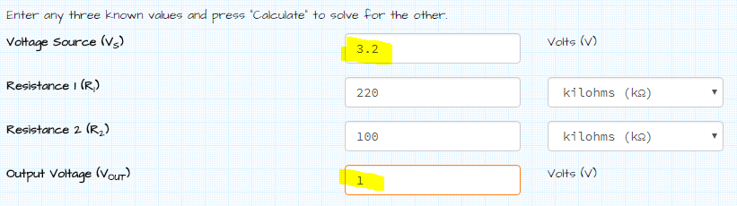
It was a while ago, but here is what I remember off the top of my head… as the Wemos & Node MCU already apply an internal voltage divider that allows up to 3.2v input on the 1v limited ADC (in theory 3.3v is allowable)
https://wiki.wemos.cc/_media/products:d1:sch_d1_mini_v3.0.0.pdf
Adding in the 180K Ohm resistor just worked with the internal voltage divider (via Ohms Law) to increase the allowable input value to 5v.
Internal Voltage Divider calculation…
Internal voltage divider with additional resistor…
Additional resistor brings one leg of the divider to 400K… maintaining the ADC limit of 1v

1 Like
Thanks for your quick answer !
According to this page 3.3 V range on the A0 analog input of Wemos D1 mini - MicroPython Forum (Archive)
the analog input pin A0 of Wemos D1 mini has a voltage divider with 220K and 100K resistors connected to the ADC input.
Having that we like to convert from 5V to 3.3V and using voltage divider calculator (Voltage Divider Calculator) with R2 = 330KOhm it gives R1 equal to 170K Ohms which is rounded up to 180K. I think this is the math behind.
Cheers!