These numbers (7, 17, 18 etc) should represent the General Purpose Input/Output (GPIO) pins of the device that you’re using. In your case, you’ve said that this is a NodeMCU.
I’m guessing that you’ve found this code from something that was written for an Arduino Uno or Mega, which have more GPIOs available for use than the NodeMCU that you’re using.
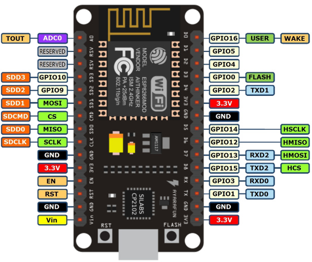
To confuse you even further, the NodeMCU has “D” numbers screen printed next to the pins, which don’t correspond to the GPIO number of the pin, and some of the NodeMCU pins aren’t suitable for controlling relays etc because they behave in a particular way when the device is booted.
Take a look at this post:
and a pinout chart for your device like this:
Also, this code wont compile correctly, becaise you’re missing some closing curly brackets.
BLYNK_WRITE(V3) { // pump fill duration input in app
  fillTime = param.asInt();

BLYNK_WRITE(V4) { // delay between pmp stopping and valves opening
  releasedelay = param.asInt();

BLYNK_WRITE(V5) { // valve 1 selection switch
  fillTime = param.asInt();
I’d reccomend that you lay out your curly brackets differently, so that the code is more readable:
BLYNK_WRITE(V3) // pump fill duration input in app
{
  fillTime = param.asInt();
}

BLYNK_WRITE(V4)  // delay between pmp stopping and valves opening
{
  releasedelay = param.asInt();
}

BLYNK_WRITE(V5)  // valve 1 selection switch
{
  fillTime = param.asInt();
}
The variable names you used in the above code don’t match those that you’ve declared at the top of your code:
long fillduration;
int releasedelay;
int duration;
and you’ve used fillTime in both your V3 and V5 BLYNK_WRITE functions, presumably because you copied and pasted and didn’t change the variable name afterwards.
Pete.