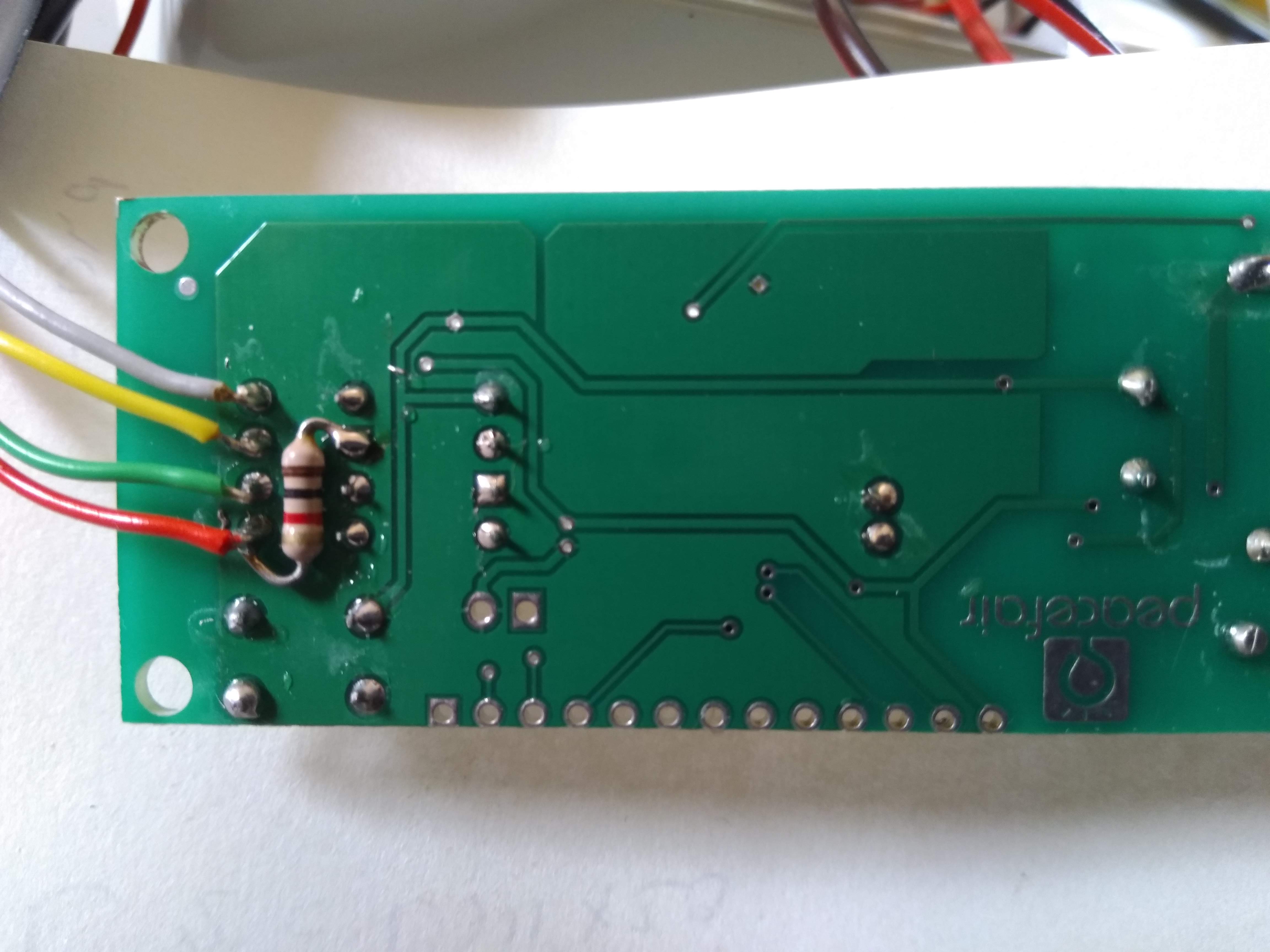
There is a " 1k ohm Resistor " at the back of PZEM Module HERE (optional)
Details are in this link:
I have already seen, but nothing to do on the internet show the. version 1.0.
That guide is for the old version 1.0 I have V3.0 and different circuitry.
I tried a USB-TTL converter but nothing works the same.
I’m using version 3.0, the one with white optocouplers.
As the PZEM-004T expects 5V serial data and the WEMOS D1 mini only provides up to 3V3 the expected optocoupler input power of the PZEM-004T has to be reduced. This can be accomplished by soldering a 1k resistor between the joints shown below.
for that part v1 is like v3


Connect the serial interface of the WEMOS D1 mini with the serial interface of the PZEM-004T.
I asked you which version of rage WEMOS D1 you are using, and how you are connecting it.
The D1 R1 is a very old board which has different pin designations to the D1 R2 and the D1 Mini is different again.
So, please say which version of the Wemos D1 you are using, ang how you are connecting it to the PZEM board.
Pete.
if you’re computer doesn’t receive anything, your board is defective.
Still some hope exists, as it might be the serial bridge is faulty or wrong connected. Generally speaking I still own three of these boards and decided NOT to use them. I don’t like its design and found those (below) cheap (relatively) ready meters a better choice for three phase solutions.
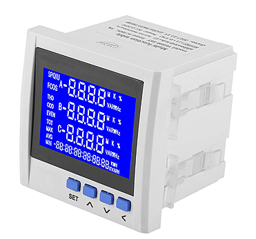
I bought this one and I’m very happy.
it works like a charm.
Using the WEMOS D1 Mini PRO, connecting: D7 + TX PZEM, D8 + RX PZEM. These are the links I make but nothing works, I don’t see anything in the serial window.
if you don’t see anything on your computer with USB converter you can’t run your sketch anymore.
to communicate
TX PZEM to ----> RX WEMOS D1 mini
RX PZEM to ----> TX WEMOS D1 mini
see picture
Ok ok how do I set PIN as the code? (2,3)
Well, this won’t work!
The D1 Mini/pro has one and a half UARTS.
UART0 is connected to he USB socket and also to pins Tx and Rx. And is used for programming the device.
UART1 is Tx only and is connected to pin D4.
If you need to have Tx/Rx communications with a peripheral such as the PZEM then you’ll need to use UART0. If you also want to use a serial monitor to see debug output then you could connect an FTDI to D4.
Pete.
WEMOS D1 mini TX is GPIO1
&
WEMOS D1 mini RX is GPIO3
I suggest to use Tasmota to check if your Board is OK (easiest solution)
or
use NodeMCU V3

Code : Is HERE
Ok I’ll try and let you know what happens, thanks Mille for technical support.
Ok I’ll try and let you know what happens, thanks Mille for technical support 
Hello !
According to the specifications given for v.3.0 of PZEM-004T it measures/reports also the frequency and the power factor. I’m not sure if the library https://github.com/olehs/PZEM004T is able to read these new electricity parameters.
Did you run any test how to read those parameters apart voltage,current, power and energy ?
Thanks !

